Other Parts Discussed in Thread: THS3091
Tool/software:
Hello,
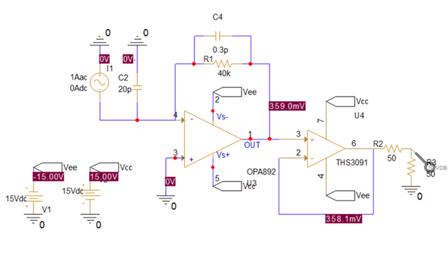
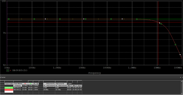
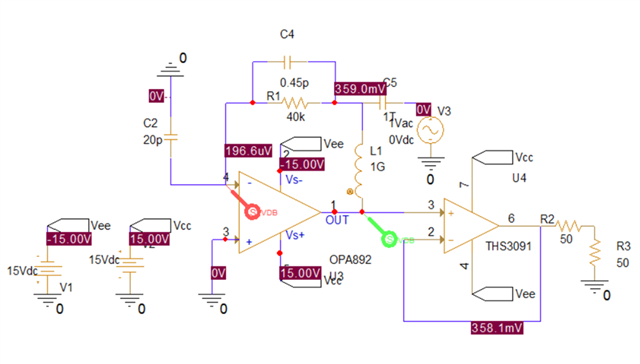
I am currently designing a TIA circuit with a bandwidth of approximately 10 MHz. The circuit is as follows:
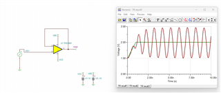
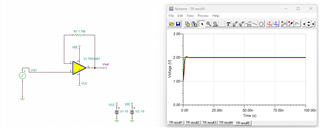
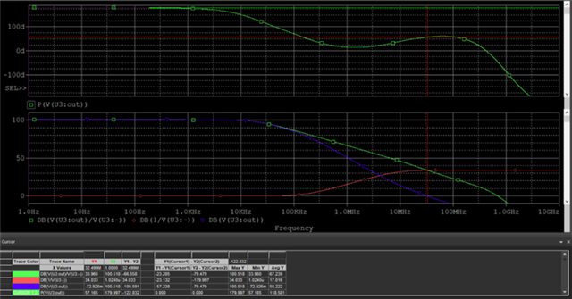
Previously, in a circuit without a buffer, I was able to analyze the phase margin by examining the loop gain using an inductor and capacitor.
However, I encountered an issue where, to achieve the maximum voltage output of the OPA892, I need approximately 260 mA of current in a 50-ohm system (assuming a 13V output). To address this, I added a buffer circuit.
I have a few questions regarding this design:
1. Phase Margin Analysis with a Buffer
In this case, is it still valid to analyze the phase margin using the same method as before (loop gain analysis with an inductor and capacitor)?
2. Stability of the Buffer Circuit
I have configured the buffer circuit by directly feeding back to the inverting terminal. Are there any additional steps I should take to ensure the stability of the circuit?
3. Optimal Phase Margin
I understand that a phase margin between 45° and 60° is generally considered appropriate. However, I have come across some documents suggesting that a phase margin of around 70° might be beneficial for high-speed control applications. In my case, what would be the optimal phase margin?
I appreciate your insights. Below, I have attached details of my circuit for reference.
Have a great day!