A related question is a question created from another question. When the related question is created, it will be automatically linked to the original question.
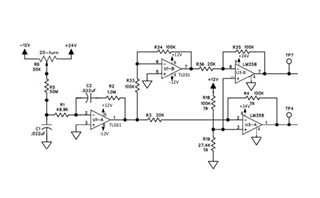
Part Number: LM358 Other Parts Discussed in Thread: TL031
Tool/software:
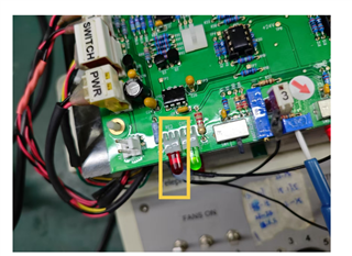
During the FCT test, it was found that the alarm light did not go off, and it returned to normal after replacing it with another batch. Please help to see what the reason is, thank you
I agree with Clemens. TP4 and TP7 are likely responsible to drive the LEDs. The voltage amplitudes at TP7 and TP4 depend on the potential resistor setting. The output of the circuit gets readily saturated in both TL031 and LM358P.
Since LM358P is in DIP package (seems to be placed on a socket), replace LM358P on the "bad" board, you should know which op amp is likely damaged. It is also that nothing is damaged due to the potential voltage settings. In other words, turn the pot slightly one way to turn on one LED; opposite direction will turn on the other LED due to the integrator.