Part Number: INA3221
Tool/software:
I need to re-open to summarize the connection of status signals in positive and negative voltage and current monitoring.
INA3221 has the following four status signals.
Critical (9): Digital output: Conversion-triggered critical alert; open-drain output.
PV (10): Digital output: Power valid alert; open-drain output.
TC (13): Digital output: Timing control alert; open-drain output.
Warning (8): Digital output: Averaged measurement warning alert; open-drain output.
In case of positive voltage and current monitoring, we connect Vs (4) to +3.3 V and GND (3) is connected to power supply ground at 0 V ideally.
If we don’t need to read the above-mentioned four status signals, then connect them to GND (3).
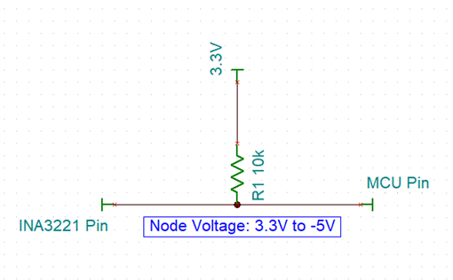
If we need to read the above-mentioned four status signals through MCU, we use separate pullup 10 k ohm resistor for each of these signals and connect to Vs (4). In our case Vs (4) is +3.3 V.
In case of negative voltage and current monitoring, we connect Vs (4) to 0 V and GND (3) is connected to -5 V.
If we don’t need to read the above-mentioned four signals, then connect them to GND (3). The GND (3) is connected to -5 V.
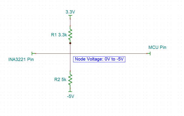
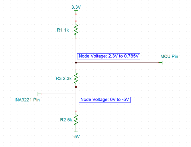
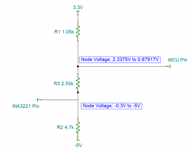
However, if we need to read the above-mentioned four signals through MCU, then how do we connect them to MCU without an isolator. Please suggest.
The VPU (16) is directly connected to VS (4) in both positive and negative voltage and current monitoring.