OPA392: Question and Request about PSpice Model of OPA392

Part Number: OPA392
Other Parts Discussed in Thread: TINA-TI

Tool/software:

Hello, 
This is Kwonjoon Lee from Samsung Display.

I would like to ask about PSpice model of OPA392.

(Detailed Question and Request)

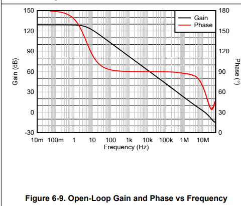
1. My open-loop phase response (especially, 1MHz-50MHz) obtained from the PSpice model of OPA392 & LTspice is quite different from the open-loop phase response in the Figure 6-9 of the datasheet.

2. I would like to ask if OPA392's PSpice model is accurate model.

3. If you want to get my LTspice simulation files, please let me know your e-mail. I will send to you my LTspice simulation files for cross-check.

Best regards,
Kwonjoon Lee

  • Kwonjoon

    I am sorry to hear of your simulation issue.  While I cannot assist you in your LTspice simulation problem, is there a chance of you simulating in TINA? many times the models are compatible but we primarily test in our platforms only.

    Chuck

  • Hello, Chuck Sins,
    this is Kwonjoon Lee.

    I would like to apologize for your inconvenience.
    As you mentioned, I will check OPA392's TINA-TI model in TINA-TI environment.
    In the case that there is a discrepancy between the model and the datasheet, I will let you know.

    Best regards,
    Kwonjoon Lee

  • Hello, Chuck Sins,
    this is Kwonjoon Lee from Samsung Display.

    I have checked open-loop gain & phase response of OPA392's TINA-TI model in TINA-TI environment.
    However, the open-loop gain & phase response of the TINA-TI model is different from that of the datasheet (especially in 1MHz-50MHz of Figure 6-9).

    Could you improve the MHC (model-hardware correlation) of OPA392 as soon as possible?
    (Our OK2FAB due date is 3/28, and quantity of OPA392 is much more than 3ku)

    (Schematic)
    1. Simple analog buffer amp. with unity-gain feedback configuration has been used, but inductor(10000TH) and capacitor(1TF) are inserted into the feedback path.
    2. VCC = 5.5V, VIN(+) = 2.75V, VCM = 2.75V, Zload = 10kOhm || 100pF.

    Best regards,
    Kwonjoon Lee

  • Kwonjoon Lee,

    The final circuit is not going to be used in an open loop. How do you plan to use the op amp?

    They look the same to me.


  • Hello, Ron Michallick,
    this is Kwonjoon Lee.

    The dual feedback analog buffer amp. has been implemented with OPA392.
    As you mentioned, OPA392 has been used with feedback configuration.

    In my opinion, the high-frequency negative zero in the open-loop phase response has not been modeled.
    As a result, the increase of phase in the open-loop phase response (at 30MHz-50MHz) has not been reflected in the model.
    Also, the phase margin of the datasheet is about 60 degree, whereas the phase margin of the simulation is about 45 degree.

    I am worried about the case that the above-mentioned discrepancy has an impact on a stability of the dual feedback analog buffer amp.

    I would like to request improvement of MHC(model-hardware correlation) of OPA392.

    Best regards,
    Kwonjoon Lee

  • Kwonjoon Lee,

    The dual feedback analog buffer amp.

    Like this?

    As a result, the increase of phase in the open-loop phase response (at 30MHz-50MHz)

    Those frequencies are beyond the op amp bandwidth. They can be wildly variable inside DUT and externally variable due to test set up imperfections. I doubt this will matter at all. 

    I would like to request improvement of MHC(model-hardware correlation) of OPA392.

    It is difficult to tweak all the AC parameters in the model, they interact with each other. They did the best they could. So this won't happen.