


Tool/software:
1. 
2. 
3.
I previously asked a related question, but since it wasn't clearly resolved, I'm asking again.
This is the link to the question I posted:
https://e2e.ti.com/support/amplifiers-group/amplifiers/f/amplifiers-forum/1495541/opa855-output-bias
In conclusion, the PSpice model (.olb) file officially provided at https://www.ti.com/product/ko-kr/OPA855 does not seem to work properly.
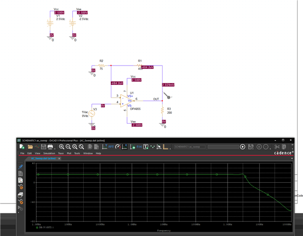
The first image shows the result of simulating the circuit as it appears when opening the .opj file.
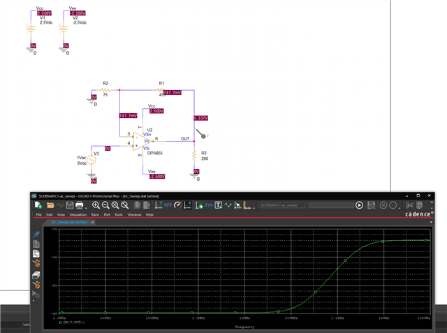
The second image shows the result of running the same simulation after replacing the component using the .olb file in the same circuit.
I believe these two should not behave differently.
I consider the first image to show the correct behavior.
I don’t understand why such a high output bias appears in the second image.
The third image shows the original circuit from the .opj file again, but the supply power was changed from double-sided to single-sided.
Although the output bias is not as high as in the second image, it is still quite elevated.
Since no separate bias was applied in the non-inverting amplifier configuration, shouldn't the output bias be close to 0?
It is clear that this device supports single-sided supply, and even after reading the datasheet, I can’t figure out the reason for this behavior.
