This thread has been locked.

If you have a related question, please click the "Ask a related question" button in the top right corner. The newly created question will be automatically linked to this question.

TLV1871: How to use this TLV1871 for Inverting and Non-Inverting with Hyteresis

Part Number: TLV1871

Tool/software:

Hi TI Team,


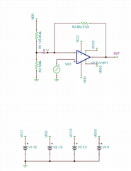
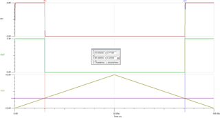
I'm planning to use  TLV1871 op-amp as a comparator. In my case the input voltage can swing from +5v to -5v ( I have to design a hysteresis model to avoid noise spikes), and my input side supply will be +12v and -12v, and output side supply can be 3v3 and Gnd. I tried checking for the application notes for this op-amp to use as inverting and non-inverting comparator, but found none. So, can I use this as comparator to detect threshold at +ve peak, and use one more for detecting the -ve peak. I have used +3v3 and Gnd at output, so that I can directly route this signal to the MCU. Provide me the proper design guide for this purpose, or kindly suggest me a best solution for the above problem statement. Thanks in advance.

  • Hi Karthick,

    Implementation of external hysteresis will be similar to the calculations in these circuit cookbooks:

    Inverting comparator with hysteresis circuit (Rev. A)

    Non-inverting comparator with hysteresis circuit (Rev. A)

    In the case of the TLV1871, there will be no pull-up resistor with your Vi swing being your +/-5V and voltages at the Vo node being 3.3V and GND.

  • Hi, actually I tried the example circuit, that itself looks like not working for me. I tried non-inverting, with the same value what they've suggested. But I don't know what's wrong with this circuit,. I have attached the image of the circuit. Please, guide me to develop the circuit for comparator. Also, in case of inverting comparator, I have to keep threshold for comp_out at negative level, I'm not sure how to make it work. Like, in my case let's assume my input swing will be +-5v, and I've to make the comp trigger out at -4.8 to -5v. Thank you.

  • Hi Karthick,

    I apologize, but I wasn't able to get to your question today. Let me get back to you on this tomorrow.

  • Hi Karthick,

    I read your reply. You cannot copy the same resistor values as the ones shown on the circuit cookbooks as your use conditions are different. Your use case has different switching thresholds as well as the output not being open-drain.

    Please read through the cookbooks thoroughly to get an idea as to how to choose your resistors.

    I'm not entirely sure why you want the VL switching threshold to be at -5V as that is the minimum swing of your input signal, but I went ahead and went through the process exactly as described in the circuit cookbooks I shared with you to determine the following resistor values:

    TLV1872_HYST.TSC