This thread has been locked.

If you have a related question, please click the "Ask a related question" button in the top right corner. The newly created question will be automatically linked to this question.

OPA365: Adjusting the Pulse width of a circuit

Part Number: OPA365
Other Parts Discussed in Thread: LMH13000,

Tool/software:

Dear Team,

This is the continuation of this question.We are doing a discrete circuit implementation of an IrDA transceiver.

We made the proto board and it is working in low speeds.The complete circuit is given below.
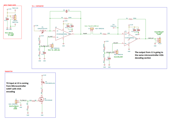
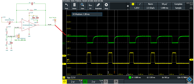
Let me show the wave-forms at each section of this circuit.In all waveforms Yellow is the transmitted signal.Going to the Gate of Mosfet.Respective output at each section are shown in Green

TRANSMITTER:

TIA
Comparator:

You can see from the above images that,the width of the pulse is increased compared to the pulse width of the TX signal.The TX signal pulse width is 21.5uS and at the comparator output the pulse width is 42.5uS.

What my firmware engineer suggest is that if we can make the pulse width of the comparator output also in the range of TX pulse width(21.5uS) is good for the system.

May I know is there any method to adjust the pulse width in this circuit or by adding some additional components?

The datasheet of all components is given below.

Microcontroller

OPAMP

Comparator

Transmitter

Photodiode

  • Can i say that TIA circuit is having a poor fall time which you want us to improve ?
    Also on the Tx side do you think a part like LMH13000 might help to drive the LED  at faster pulse width , or control the LED output drive ?

  • May I know is it because of low speed comparator.

    May I know how to improve the fall time of TIA

  • Okay let’s start with few steps

    1) disconnect the comparator and check if your opa365 recovers much faster . Send oscilloscope shot of opa365 output without comparator connected . 

    2) stability wise it looks good and simulation wise also it seems good . 
    let’s start with disconnecting the comparator 

  • The second image is OPA365 output.I removed the jumper(Comparator is isolated)

  • okay so lets continue with jumper removed ( J5 removed and J2 mounted always )

    i think comparator is working fine so lets concentrate on the OPA365.

    Tina simulation is showing only 1us of overdrive recovery time where as you are getting ~ 100us which is what we need to debug.

    Lets try the below options

    1)  Try reducing the gain ( maybe 20k or 2k in feedback ) so the OPA365 doesnt saturate so hard.

    2)  Probe all pins of OPA365 when you run this test and share waveforms.

    3) Are you sure the LED turn off cleanly when the switch is off , can you measure the current across R9 with two channels and zoom in during rize and fall to ensure the current indeed goes to zero. It maybe happening there is some small residual current remaining in LED as you turn off which is being picked up by RX and since you have gain of 200k, OPA365 maybe recovering slowly.

  • Thank you.

     I will do all these things and update you..