This thread has been locked.

If you have a related question, please click the "Ask a related question" button in the top right corner. The newly created question will be automatically linked to this question.

OPA188: Calculating of RTD in Analog linearization of RTD formula


Tool/software:

Hi,

I came across the very interesting slyt442.pdf, which deals with resistance temperature detectors (RTDs). I also found Bruce Trump's PowerPoint presentation (Annotated math solution.ppt), which shows how to rearrange the formulas using Mathcad.

slyt442:

The final equation is solved for VO and contains only one unknown — namely the RTD resistance R(RRTD) itself. So I thought I could simply rearrange the formula to solve for RRTD, plug in the VO value measured by the ADC, and get the corresponding resistance.

But unfortunately, it seems to me that the formula isn’t truly solved for VO, but rather for RRTD, and just labeled with VO. Could that be the case?

"Annotated math solution.ppt": 
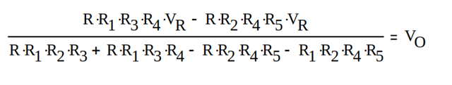
So my question is:
How would the formula look to calculate RRTD if you only have the output voltage VO measured by the ADC connected to the opamp output?
Do you also need to know the current through the RTD, since it's essentially driven by a constant current source? That seems a bit imprecise to me...

Thanks a lot for your help!

  • Chris,

    Below is a power point that shows the derivation of the equations for VOUT and RTD.  The RTD equation provides a value for RTD based on VOUT, VREF, and the resistor values.  I checked the results with TINA and it worked well.  Note that resistor tolerance and VREF tolerance will add significant error.  I think when this method is used the objective is to cancel the non-linearity and calibration is used to correct for tolerance errors.  This method was popular in the 90's and early 2000's for analog only RTD conditioning.  The alternative is to mathematically correct the ADC measurement using the Callendar Van Dusen equation or a lookup table, rather than using analog linearity correction.  A Basic Guide to RTD Measurements is a great document on RTD that explain this method.  I only mention this as I think the mathematic correction is probably the best approach when an ADC is being used.  I think this method is practical when the signal path is pure analog (i.e. an op amp or current transmitter).

    Here is the document and TINA source files:

    RTD-linerization-Aug-5-2025.pdf

    RTD Linearazation.TSC

    Best regards, Art 

  • Hello Art,

    thank you very much for the derivation. It works well for me, too.

    Best regards, Chris