A related question is a question created from another question. When the related question is created, it will be automatically linked to the original question.
If you have a related question, please click the "Ask a related question" button in the top right corner. The newly created question will be automatically linked to this question.
Sorry for delay, I got sidetracked on another project...
I set up another INA219 with a PWM driver with reversing switch to a proportional solenoid valve. Power supply voltage to the PWM was 24V from a regulated power supply. This time (remember I have smoked two INA219's already) I was very careful to ensure that the Vin+ was in fact connected to the positive output from the PWM driver with the reversing switch position on the PWM driver measured positive...
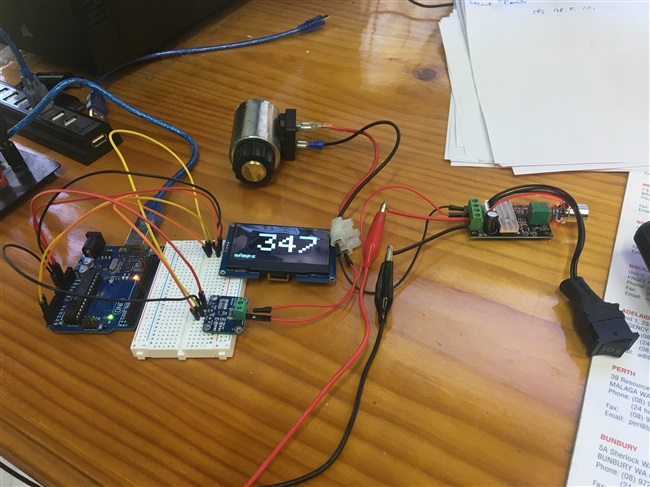
The setup is complete with Arduino UNO, breadboard with the INA219 and a 128x64 OLED display, I could attach a photo / video but can't work out how!
I turned it all on and the results were as expected, no smoke!
As soon as I flicked the reversing switch on the PWM driver ie, reversed the current flow thru the INA219 with my finger sitting atop the chip on the INA219, I burnt my finger... same as what happened with the first two... of course, I saved this one by flicking the switch off.
So there is no doubt the PWM driver is good, is it the INA219's I bought from Amazon...
Firstly, the INA219 isn't suitable for a PWM operation, I'd recommend the INA240 or INA241 instead. Secondly, if you'd like to continue using the INA219, connect it in high-side or low-side instead of in series, it may work then. If this doesn't resolve your question, please respond with schematics, scope shots or a block diagram of your setup. You can add messages by clicking on the "insert" button.
Hi Mallika To an electronics dummy , you would have no idea that the INA219 could NOT be used with PWM... Yet it does work... as you can see
in the set up the INA219 is set in the positive leg to the coil on the load side of the PWM driver thru to the proportional coil and back to the PWM driver... without doing anything to the wiring, the three position switch on the right hand side is switched over which would drive the current backwards thru the INA219 and immediately smokes the chip!
I have looked at the INA240 and yes it makes a special point of it being for PWM and I have ordered a few to try...
I have verified the current readings from the INA219 with my Fluke DMM and the readings are compatible so I think it's fare to say that the application of the INA219 in this case is okay as long as you don't reverse the current despite the data sheet saying that it can!
When I get the INA240's I'll let you know how they go
I wanted to try a different Arduino board for this project so I took the opportunity to verify the measurements I was getting with the INA219 (hooked up positive side only) with my Keysight DMM and I was more than happy with the results... hopefully the video I took can be inserted FYI...
Okay, the file is too large so I will give you a link to my Dropbox
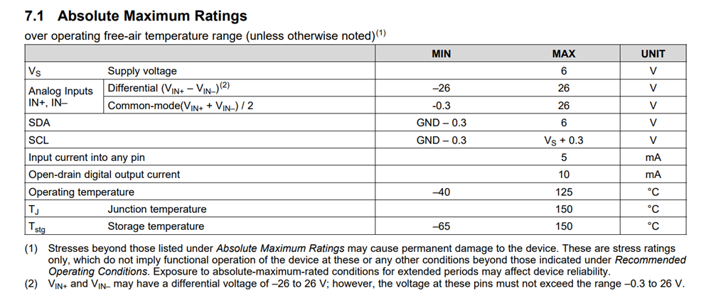
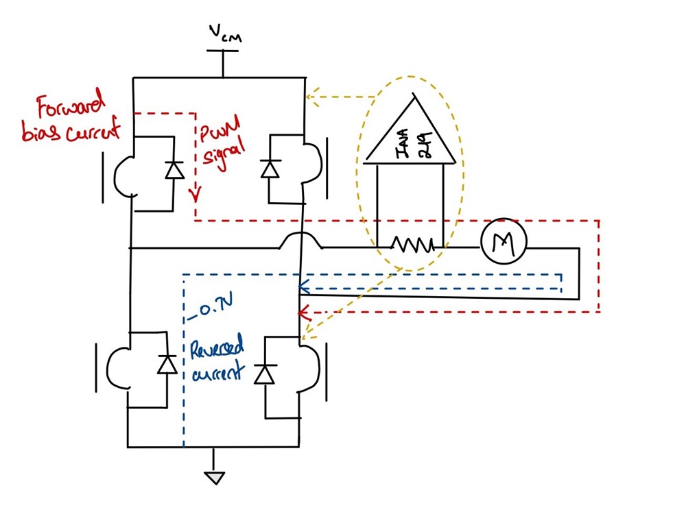
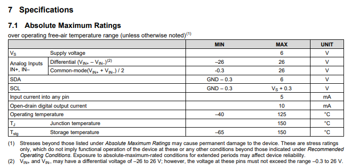
Thank you for the video and image of your setup. From your setup and description, you appear to be connecting the INA219 in line with the PWM signal. As mentioned above, it won't work for PWM because when you try to reverse the current, you will violate the common mode voltage ( -0.3V) and this leads to the device smoking up.
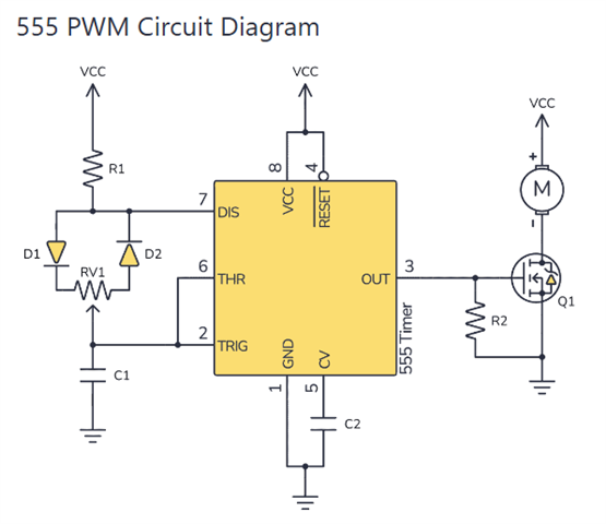
The device works when PWM is forward biased (current flowing as shown in red), but when you switch of the PWM signal, the residual current will attempt to flow in the blue path. In this case Vcm will be that developed across the bottom left diode = -0.7V. This is below the -0.3 abs max value, hence the device breaks.
As a solution, you can move the INA device to either of the two locations shown in yellow, making it high side or low side. Now, the Vcm will either be referenced to supply or ground, preventing violation of Vcm specs.
If you'd prefer to keep the INA in line with the motor, then the INA240 is your solution.
Thanks for the prompt response, that makes a bit more sense...
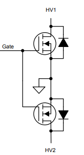
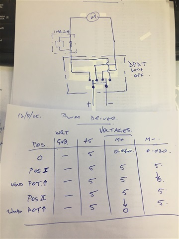
This morning I have been investigating the functionality of the PWM driver I am using and made some interesting discoveries to find it is basically as below
In between the mosfet and the motor we have a DPDT selector switch with the OFF position and the voltage table below of the motor when FWD or REV was selected was initially VCC on both legs at zero speed THEN, as you wind the potentiometer up to increase the speed the voltage falls away to zero whilst the input voltage holds at VCC which is exactly as you would see according to above schematic.
I did not fit the INA219 for this test because I did not want to cook another one but the question back to you if I may please, does this verify the function of the INA219 and the fry ups I have experienced? From what I see on my DMM and that the INA219 is bi-directional I cannot see what PWM has got to do with the failures...
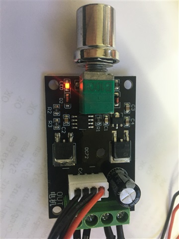
A close up photo of the PWM driver you will see the 555 clock, LR7843 mosfet the MBR1045CS back to back diode
Please connect an oscilloscope to your PWM driver + Motor circuit and observe the waveform when you reverse the switch. Check if the voltage drops below ground, if so how far below ground? Any scope shots you could share would be appreciated.
As I said, for fear of smoking another INA219, I DID NOT fit one into the test circuit above.
Yes, the FWD / REV switch JUST switches the positive output from the PWM driver which confirmed that the mosfet is on the negative...
What I will do now is fit the INA219 into the positive leg to the motor ie from Vin+ > Vin- > M+ which will be in the Vcc leg in the above schematic...
I will only run the circuit at 5V initially... I will connect the osciliscope to either side of the INA219 and then do the FWD / REV as I did yesterday...
This will reverse the current thru the INA219 and hopefully won't smoke it... standby
Below links to my Dropbox with videos of the test results as above with the oscilloscope on Vin+ and Vin- grounded to the supply... please note the supply voltage is ONLY 5VDC... I only have one INA219 left... most of the smoked INA's were at 24V !
I'm happy to run a test at 24V iff you want...
My scope isn't the smartest instrument on the block but it clearly demonstrates the reversibility of the INA reporting FWD /REV flow and I can't see any "bad" voltages on the reversing leg...
Thank you for sending the oscilloscope videos, they make the debug so much easier. When you reverse the switch, you can see the SDA line is dropping to a very negative value, violating abs max of (GND - 0.3) V. You're not smoking the INA219 at 5V, but if you keep operating the device in this manner, it will be damaged eventually. The device smokes at 24V because SDA is probably dropping to a even more negative voltage, that's causing an immediate failure.
Now in case of the INA240, it is built to handle these negative spikes so you shouldn't see the same issue.
Sorry for delay, been busy sorting out an ESP01...
Still waiting for the INA240's to arrive, will repeat the test at 24V and report back to you as soon as results available...
In this particular application there is no possibility of reversal thru the INA219 and tests so far show no indication of heat build up on the chip at 24vdc and 900 mamps thru the proportional coil so we will progress with that
I have run these up and found 2.5V sitting on the OUT pin... eventually figured out that it is to do with the REF pins which look like this board has NOT dealt with at all...
I have got it going unidirectionally and getting good results after modifications to the VREF and subtracting the 2.5V before converting to current...
Swapping polarity just changes the sign so that's okay...
I'll run 24V PWM and "switch" that shortly and record on oscilloscope but just like verification about the OUT voltage and what tgo do with the REF pins iff anything
We only deal with devices and products sold by Texas Instruments. I'm unfamiliar with the board above, our INA240 EVMs (https://www.ti.com/tool/INA240EVM) you'll see have the REF pins open to either be connected to GND ( for unidirectional sensing) or to a voltage (for bidirectional). I don't see any breakout pins for REF on this board, not sure how its routed.
I'll run 24V PWM and "switch" that shortly and record on oscilloscope but just like verification about the OUT voltage and what tgo do with the REF pins iff anything
I'm not sure I understand your question, but the REF pin's purpose is to enable bidirectional current sensing, please see section 8.4 of the datasheet for more information https://www.ti.com/lit/ds/symlink/ina240.pdf
Okay, I have belled out the board I have and can confirm it is setup as Mid Supply Voltage with Ref2 connected to Vcc and Ref1 connected to GND...
This explains everything I am seeing in testing so far, the Arduino analogue input connected to OUT was measuring Vcc/2 with no current flow thru the board...
By subtracting this 'null' value (in the case of Arduino Vcc = 5V) from the actual voltage conversion from the ADC I am getting results the same as my DMM... so all I need to do now is set it back up on the PWM
Just letting you know I implemented the Reversible PWM circuit with the INA240 breakout board this morning for testing as discussed, I have smoked the chip, exactly the same as happened with the INA219... as soon as the PWM switch reversed the current flow the smoke alarm went off!
Sorry to hear you're still facing the issue on the INA240, could you please check how large the negative spike is and whether it is within -6V (the absolute max spec).
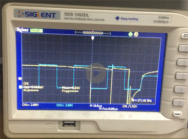
Just did some tests of the PWM reversible driver and with the oscilloscope on the driven leg grounded to the power supply I was getting Vpp's MUCH larger than 6V !
The PWM driver has a 220 microF capacitor on the power side which must be the problem!
I have spare PWM drivers, I will remove the capacitor on one and run the test again and advise