Other Parts Discussed in Thread: TINA-TI
Tool/software:
Hello,
about two months ago, I asked for an alternative operational amplifier in order to match current driving requirements of my application. There, the current feedback OPA2675 was recommended. That was a helpful suggestion.
So I built a driver for a small TEC (thermo electric cooler aka. peltier element) based on the OPA2675 with the TEC connected to the two outputs of the opamp ("bridged configuration").
The simulation helped me to figure out the correct values for the feedback network so that the opamp provides the power to the TEC with the control voltage UControl = 0 - 3.3 V (which is provided by a DAC). I included Voffset in the circuit in order to shift the control voltage but I noticed that my application does not need that and thus I set R1 = 1 TOhm.

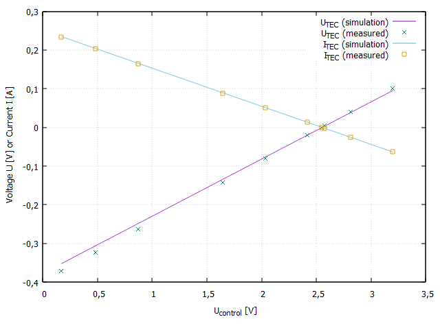
To compare the circuit with the simulation, I used a 1.5 Ohm resistor instead of the real TEC element and took some measurements: For example at UControl = 171 mV, I measure UPeltier = -372 mV (across R5) and a current of 233 mA. At UControl = 3,2 V, I measure 101 mV and a current of -63 mA through R5. The bridge is balanced (no current through R5), when UControl = UBias = Vref/2 = 2.55V.
I noticed that the simulation agrees with the circuit only if the feedback resistor Rf is set to half the value of the circuit. In other words, in the circuit I have Rf = 510 Ohm whereas in the simulation I have to set Rf = 260 Ohm in order to make simulation match the values measured on the bench.
Any idea why this is?
Please note that I have attached the Tina-TI simulation below so you have it handy in case you want to look at it.
Thanks and have a nice weekend.
Daniel