This thread has been locked.

If you have a related question, please click the "Ask a related question" button in the top right corner. The newly created question will be automatically linked to this question.

OPA547: OPA547F/500

Part Number: OPA547
Other Parts Discussed in Thread: OPA551, , OPA593

Tool/software:

We are using OPA547F/500 power amplifier. Our application requires 230-240mA current. When sourcing this, the amplifier is getting heated up. We want to insert a heat sink, but do not want to drill holes on board. Which heat sink to use?

  • Hey Akshay, 

    What are your supply rails? Are you soldering the thermal tab to V-? Ideally, this thermal tab should connect to a large copper pour to help dissipate heat. 

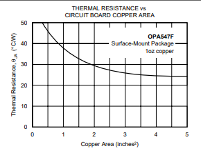
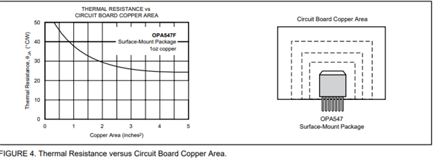
    See figure 4 of the datasheet for more information:

    There are some conditions in which an external heatsink is required, but in general it should be possible to operate the device like figure 4 shows. 

    What is the VOUT voltage when you are sourcing 240mA? 

    Remember, power dissipation is going to be dominated by the difference in voltage from V+ to Vout. 

    If we cannot alter the copper pours, then you will need to place a makeshift heatsink on the top of the device, but the thermal performance will likely not improve significantly due to the higher thermal resistance from the top of the package. 

    Feel free to send over the PCB layout pictures of the design. I can review these and tell you what I think we should do. 

    Thanks,

    Jacob

  • Hi Jacob,

    The supply rails we are using is 30V and ground. Input to the IC is 15V and we are using it as buffer amplifier. The thermal pad is connected to V- on board. We have not provided sufficient copper area, but have inserted a 0.3 square inch heat sink on top of IC. Vout is 15V since input is 15V and we are using op-amp in buffer configuration. 

  • Jacob, 

    I do not have access to layout files, but can get information required to clear your doubts.

  • Hey Akshay, 

    It is good that you are using single supply, this means that the thermal tab can be easily connected to the ground planes on your board. 

    This is the most common method for removing heat form the device. A top mounted heatsink can help, so it is good to hear that you were able to install one in your application. 

    Please let me know if you are able to obtain the design files. Pictures of the layout are okay as well. 

    In general, I am looking to see how large the thermal plane is. Per my previously included figure 4, you can see just how impactful the plane is to the thermal performance of the device.

  • Hi Jacob, 

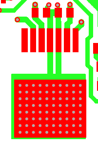
    Please find the attached top an bottom electric files I have got from team. The component which is causing the problem is shown in screenshot images. You can relate these with the top and bottom electric files.

    TOP_ELECTRIC.pdf

    BOTTOM_ELECTRIC.pdf


  • Hi Akshay, 

    Thanks for sharing the pictures of the layout, this is very helpful for me to see.

    We certainly are on the smaller side for pour dimensions, but the thermal vias also help to add surface area. 

    Assuming a Vout of 15V with ~250mA current draw, we will have a power dissipation of about (30V-15V)*.25A = 3.75W. If Ta is 25C and we want to be less than 150C Tj, we need an effective theta Ja of (150C -25C) / 3.75W = 33.333W/C. Per figure 4, we need about 1.5 square inches of copper to have sufficient heat transfer. With some design headroom, I would want to be at least 2.5 or even 3 inches of copper pour. 

    Elevated ambient temperature would make this even harder on the device if Ta was not 25C. 

    A top mount heat sink can help improve the performance, but the best bet may be to rework the copper pours. 

    Is the system working as desired with the top heatsink?

    Thanks,

    Jacob

  • Hi Jacob,

    The problem is that the PCB is already manufactured. We can't relaunch it again. We need to solve this as it is now. Heat sink is not helping. With heat sink, it worked for some time, then started to load, drawing full current from supply. Is their a way to work on existing PCB without relaunching its manufacturing. Or, can we replace the OPA547F/500 IC with any other high current op-amp IC? If yes, can you suggest its part number?

  • Hi Akshay, I do not know of another device that fits this footprint. 

    What heatsink are you using? a part number can help me figure out the thermal performance. 

    If you have good thermal conductivity to your PCB, you could even mount another small heatsink on the bottom of the PCB. 

    A HS like this may work for the bottom of your PCB:

    A similar style but smaller XY dimension could work for the top side. 

    What is this net circled in green?

    Is this not a GND plane? 

    Some customers utilize blower fan style heatsinks for our larger devices. This type of implementation could help lower the thermal resistivity to the junction. 

    When the device enters thermal shutdown, is the PCB hot in the thermal pad area? IF it is not, it may be an indicator that the thermal tab is not sufficiently connected to the thermal pad. 

    Thanks,

    Jacob

  • Hi Jacob,

    It is ok if similar footprint device is not known. If you know any other device which serves our purpose, you can suggest.

    https://probots.co.in/heat-sink-set-aluminum-for-raspberry-1.html

    You can find the link of heat sink above.

    The net circled in green is a 15V potential plane and not ground plane.

    The PCB is extremely hot in the thermal pad area. 

  • Understood on the thermal performance, I see that these are V- pours now.

    Admittedly, the OPA547 is probably one of the best devices to use if you want ~250mA out of the device. OPA551 is a similar device, but I would still likely take the OPA547 in my opinion. 

    Alternatively, something like OPA593 may be possible, but we will not have much margin if you really need 240mA. 

    Reworking the board, or going to the through hole variant with a heatsink may be the best option. 

    If you were able to add larger ground pours, we would have acceptable levels of power dissipation. 

     Thanks,

    Jacob

  • Hi Jacob,

    We will think which is the best option. Thanks for your suggestion and time. 

  • Hey Akshay, 

    I would use the OPA547 and make the thermal pour larger to help dissipate heat. 

    I can review the design before we send to fab.

    Thanks,

    Jacob

  • Hi Jacob, 

    We have decided to use DC DC converter instead of OPA547, as we expect capacitive load to be high. 

  • Hi Akshay, 

    You are correct in your thinking, the high cap load will make this more suited to a DC to DC converter. 

    Thanks,

    Jacob