OPA547: Constant AC current source

Part Number: OPA547
Other Parts Discussed in Thread: ALM2402-Q1, ALM2403-Q1, OPA567, ALM2404-Q1, OPA593

Tool/software:

Hi,

I want to design a constant AC current source of current variable upto +/-400mA. 

The frequency of the current source will be max 100Hz. 

Can somebody tell me whether Ti has a readymade solution for this?

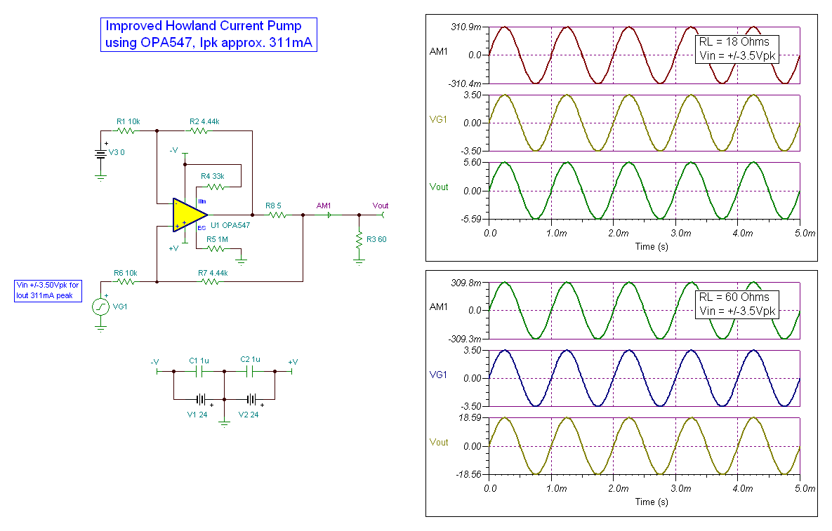
I came across Improved howland current pump using OPA547 for Ipk approx.311mA, attached below. But we required for +/-400mA and input volatge range is +/-10V.Could you please share the relevant circuit for this?


e2e.ti.com/.../constant-ac-current-source

  • Hi Lathaniveatha,

    You are on the right path here, yes the OPA547 is the most suited device for your application requirements.

    What are your accuracy requirements in this application? What input range do you want for this design?

     I can design similar circuit for your desired implementation.

    Thanks,

    Jacob

  • Hi Jacob, 

    Thanks for your reply.

    The input voltage range is ±10V, and the required current is approximately ±400mA.The OPA547 appears to be quite expensive.If possible, could we use a more cost-effective alternative that provides similar performance?

  • Hi Latheniveatha, 

    Thank you for clarifying the input range. What supply rails do you intend on using? We may have options here depending on the required supply voltages present.

    If you could use +-12V or less, I would go with two ALM2403 channels in parallel (though this is more complex).

    Thanks,

    Jacob

  • Hi Jacob, 

    Input supply rails used -> +/-15V. Could you pls suggest circuit for this voltage range?

  • Here you go:

    Howland 400mA.TSC

    Is this design suitable for your needs?

    Thanks,

    Jacob

  • Thank you for sharing the design.

    We've observed that the circuit behavior changes with higher load resistance. Could you please share for the below requirements:

    • Input supply: ±15V

    • Output current: ±400 mA

    • Load resistance: 5 to 100 Ω

    Could you confirm if any of the resistors or the op-amp IC are subject to significant power dissipation under these conditions?

    Also, since the OPA547 is priced around $6, is there a more cost-effective alternative op-amp that could be used for this application?

  • Hey Latheniveatha,

    These project requirements are not possible to realize. 

    100Ohm load with +-400mA Howland would be +-40V across the load. Do we really need 100Ohm up to 400mA? 

    I am not familiar with any other device in this category with a cheaper price. Reducing output current or supply max may help us get to a lower price device. 

    Thanks,

    Jacob

  • Hi Jacob, 

    Apologies for the confusion earlier. The shared circuit appear to be appropriate. Yes, we can reduce the supply voltage to ±5V if that allows for a lower-cost solution. Could you please clarify the relationship between the input voltage and the output current? We're aiming for an output current range of ±10 mA to ±400 mA, and the input voltage is a square wave max +/-10V.

    Also, could you confirm whether any of the resistors or the op-amp IC would experience significant power dissipation under these operating conditions?

  • Hi Lathanveatha,

    Yes, +-5V would help greatly with cost of the IC. The challenge is in that we will run into simple V=IR problems. Even if we made a perfect ideal howland current pump, we will never be able to make 400mA through 100Ohm V=.4A*100Ohm = 40V.

    This means at minimum we would need a V+ rail up to at least 42 to 45V to make this possible.

    If we reduce to +-5V, we would even more output swing problems (though we would have a cheaper device we could use).

    R3 in my schematic will have the highest power loss in the system. 

    Do you need 400mA at 100 ohm?

    Our gain is about 40.5mA/V in the current setting. We can always easily change this scaling factor as needed. 

    Best,

    Jacob

  • Hi Jacob, 

    At 100 ohm - 50mA and at 5ohm load - 400mA. Could you please share for +/-5v supply voltage with cost effective IC. 

    Also could you please share the recommended footprint for the part (OPA547).

  • Hey Lathaniveatha, 

    Please consider using ALM2402-Q1 for this function. 

    If you want to make 50mA at 100Ohm, you will need more than +-5V supply. Something like +-6V supply would be ideal for this. 

    Consider any combination of load which generates about 5V Vout to be the maximum we recommend. In other words, if you wanted to know the maximum load current you could generate at 20Ohm, we use V=IR to determine this to be 250mA max. 

    Here is 100Ohm Load, I = +-50mA, generated with +-1.25V input:

    Here is 5 Ohm Load, I=+-400mA, generated with +-10V input

    Here is 20 Ohm load, I = +- 250mA, generated with +-6.25V

    Thanks,

    Jacob

  • Hi Jacob,

    We have simulated the circuit you shared using the ALM2402 (img attached). However, at a ±10V input, we are observing an output current of ±550mA instead of the expected ±400mA.

    We used the simulation model from the TI website. Since we couldn’t access dual-channel pinouts, we simulated using two ALM2402 ICs.

    Also, could you please confirm if the ALM2402 can operate with a ±15V supply? I have attached the table of required output current and voltage.Output voltage from 0.47 to 5V. Alternatively, if we ignore the 50mA at 100Ω condition, is it possible to use the device with a ±5V supply?

    Lastly, could you please share the formula for calculating the resistor values?

    Thanks in advance!

    Load resistance ohm Current
    mA
    Voltage out
    V
    23.5 20 0.47
    23.5 30 0.705
    100 10 1
    11 150 1.65
    100 20 2
    50 40 2
    5 400 2
    15.67 200 3.134
    23.5 200 4.7
    100 50 5
  • Hi Lathaniveatha,

    In short, all of the ALM240x models have quirks which may not be perfectly representative of the actual device performance. Due to this, I simulated using an ideal model, and consulted the datasheet for confirmation as for if I believed this would work in real implementation. 

    Sorry for not sharing my sim files in my last post. You have done a great job of replicating my simulation, TINA however decided to not connect R4, R%, and C1 together (see lack of a dot at this intersection). 

    Since there is little feedback mechanism here, we are actually stuck at VOL, and the slight changing in AC current is due to the model having some common mode dependencies:


    All being said, even if we did connect this feedback, we would still see that the ALM2402 model does not want to output 400mA under certain scenarios. 

    Again, I know that the real device will do so, this is just a claw limit issue with the model. 

    I still believe there will be some error associated with the small 1 ohm RHCP resistor in the original design I suggested. You asked for the formula, and hopefully this will help illustrate why this can be impactful:

    Iout = {G x (Vp -Vn)}/ RHCP

    G= Rf+RHCP/Rin when the following is true:

    RF=RFP

    Rin1=Rin2

    RHCP=Rcomp

    For this new design, I have a gain of 

    Iout = {(1005/5000) * +-10V)}/5 = +-.402A

    trace resistance will add to this RHCP resistor, and resistor mismatch will add more error to this design. Generally, we want to make RHCP large enough to help with gain error, yet not make it so large that we see large power losses in the Howland resistor.

    Howland ALM2403.TSC

    Some of my influences for this change:

    ALM2402 has a max Vs of +-6V. This is fine because this device has a high Iout and better swing to rail than other ALM240x devices. A challenge is in that we are trying to input +-10V, so we cannot directly connect this to the device inputs as this would cause damage. I had put an attenuator followed by a buffer to solve this problem, but this introduces more error. 

    With this new design, we are connecting the ALM2403-Q1 which can be supplied by up to +-13V supply, so we no longer need the input attenuator. Consequently, we can now raise the value of the RHCP resistor as we now have more voltage swing on the larger supply rail. This will cause more power loss in the chip, but we can expect slightly less error with this new design. The LAM2403-Q1 also has weird modeling quirks, but I am able to do 50mA at 100 ohm and 400mA at 5 ohm with this new design. Rest assured the real design will likely perform even better than this design when it comes to swing to rail performance. 

    If you wanted more security/ better performance, we could even place the second ALM2403-Q1 channel in Howland parallel with the first channel to make sure we can always do +-400mA over temperature and process variation. 

    Let me know what you think of the designs. 

    To put simply, I believe both solutions have their advantages. Generally, the new design is a bit more sound so long as we can tolerate the higher power loss in the chip.

    Does this application make AC current, or is this a DC current source?

    Thanks,

    Jacob

  • Hi Jacob,

    Thank you for sharing the circuit and simulation model.

    We do have some limitations on our end— the op-amp supply voltage we can only provide either ±15V or ±5V. Also, there are no strict requirements for the input voltage to be exactly ±10V. Our primary objective is to achieve an output current of at least 400mA, or 200mA minimum.

    Thanks for providing the formula, we'll go through it.

  • No problem,

    Thanks for the information on supply requirements. IN this case, we may then be better off with the ALM2402-Q1 on +-5V supply. 

    Again, there will be some complications with this model, but please let me know what you end up looking to design. 

    I am happy to help work to realize a valid solution.

    Thanks,

    Jacob

  • Hi Jacob, 

    Thanks for your support.

    We tested the circuit you shared and observed that changing the op-amp supply voltage impacts the output current. Is there a known relation between the supply voltage and the output current?

    Could you also help us with recommendations for achieving up to 400 mA (or 200mA) output current using op-amp supply voltages of ±12 V and ±5 V? The input voltage can be adjusted accordingly based on the supply.

    Additionally, apart from the OPA547 (which is a bit expensive for our application), are there any other cost-effective op-amps that can operate at ±15 V and deliver up to 200 mA or 400 mA output current?

  • Hi Lathaniveatha,

    Thanks for your patience through this design process. 

    You are correct, these models have dependencies on supply voltage.

    In the model, we have these blocks called CLAWN/P. These blocks help the OPA understand what the max Vout is relative to IOUT. This is all made relative to the supplies, so it is very common to see that Higher VS results in higher IOUT capacity. 

    Here is the claw block form the model:

    +-12V could be accomplished using ALM2403-Q1, though the sourcing IOUT may be a bit weak if the device heats up. This means we cannot guarantee that the device will always function. 

    +-5V would be best covered by the ALM2402. I understand that the model may not perfectly show device performance. IT may be possible to purchase an EVM an try this in real life. Alternatively, I may be able to configure the device like you want and measure this in lab for you, though it may take some time on my end to get this setup. 

    +-15V would best be covered by two options: up to 200mA OPA593 (more expensive than OPA567). The best of the two, ALM2404-Q1 will be cheaper than the OPA567, but this device has not yet released. I believe we are still planning APL for this device in Q4 of this year. This device however will only be able to do 200mA, for your application. 

    In my eyes, the best option would be to put one ALM2403-Q1 chip in Howland parallel to guarantee performance at 400mA. 

    This article covers how I would implement on ALM2403-Q1:

    Parallel Amplifiers for Higher Output Power: An Improved Howland Pump Approach

    This solution would be cheaper than OPA547, offer better performance, and smaller solution size. 

    Let me know what you think.

    Best,

    Jacob

  • Hi Jacob, 

    Thank you for your suggestions and for sharing all the required circuit details.

    We’ve decided to proceed with the ALM2403-Q1 using a ±5V supply voltage providing +/-400mA current, Input voltage can be set to ±4V as needed. We have tried the circuit with ±5V supply, but we are unable to get the expected output.

    Could you please help us simulate the circuit under these conditions? We’re comfortable proceeding with this setup.

  • Hey,

    ALM2403 is not a vey good current driver at +-5V. If we want to use +-5V, we should proceed with ALM2402. We could use ALM2403 if we use higher rail voltages like +-12V.

    Input of +-4V will certainly help keep everything good range of the device, but we still might need to use a small divider to keep the votlages within the common mode limitations of the device. 

    What produces this +-4V signal?

    What is the maximum load used on the system with 400mA? As is, I would imagine we would get anywhere from 6 to 10Ohm max with 400mA load on a +-5V rail.

    Thanks,

    Jacob

  • Hi Jacob, 

    Yes +-5V with ALM2402 also fine. Could you please share this on urgent basis.

    The ±4V input will be provided by the DAC, 400mA connected to 5 ohm load. 

    The corresponding output voltage range would be approximately 0.47 V to 4.7 V, based on the following conditions:

    • 0.47 V corresponds to 20 mA across a 23.5 Ω load

    • 4.7 V corresponds to 200 mA across a 23.5 Ω load

    Load resistance ohm Current
    mA
    Voltage out
    V
    23.5 20 0.47
    23.5 30 0.705
    100 10 1
    11 150 1.65
    100 20 2
    50 40 2
    5 400 2
    15.67 200 3.134
    23.5 200 4.7
  • Hi Lathaniveatha,

    Perfect, this table is very helpful. 

    We are good on all of these though 23.5 ohm at 200mA may be a bit tough. Due to the drop across the output stage transistor, we may run into non-linearity.

    We still need to use an RHCP resistor to control the current source. are you able to have all conditions be below 4.5V vout?

    Thanks,

    Jacob

  • Hi Jacob,

    We’ve finalized the operating conditions: we will be supplying the op-amp with ±7V and providing an input voltage of ±5V. Our goal is to achieve a maximum output current of 200 mA (with single opamp) and 400 mA (with dual opamp), as per the load resistance values previously shared.

    Could you please confirm if these conditions are supported by the ALM2402-Q1

    Additionally, we would appreciate it if you could share a reference circuit using the ALM2402-Q1 that meets the above input and supply voltage conditions while delivering both 200 mA and 400 mA outputs.

    I believe a single op-amp should be sufficient for delivering 200 mA output current, while for 400 mA output, we plan to use both channels of the dual op-amp.

  • Hi Jacob, 

    The ALM2402-Q1 has only VCC and GND pins. Could you please clarify how a negative supply can be applied in this case, or if it's possible to configure the device for bipolar output operation?


  • Yes, I understand how this can be confusing. 

    GND is VEE to the ALM2402. We call it GND because most users do not use split supply with this part. You are welcome to connect negative voltages to these pins so long as you follow ABS max supply requirements.

    Notably, the SHDN circuitry will now need to be biased to a negative voltage, but this can be accomplished through various means. 

    Thanks,

    Jacob

  • 400mA would certainly be best suited with two amps, correct.

    +-7 is fine for the device, and this will offer great benefit to the operation. You may be able to get away with using one channel for 400mA, but more testing will help us understand where this limit lies. 

    Thanks,

    Jacob

  • Hi Jacob,

    Thank you.

    Could you please share the circuit for this configuration with ALM2402-Q1?
    Supply: ±7 V
    Input: ±5 V
    Output Current Requirements: both for 200 mA and 400 mA

    We’re unable to fully understand the relationship between the supply voltage and output current, so your guidance would be appreciated.

  • No problem,

    This curve tells the maximum output voltage possible for the amplifier at 5V supply, and the x-axis is output current. 

    As we increase output current, we see that we cannot swing as close to the rail. For example Figure 1 shows that at 25C and 100mA, I can typically expect a maximum output voltage of about 4.952V. Alternatively, If I source 350mA, I see that my maximum output voltage on a 5V rail now becomes about 4.83V. These curves do not change shape much with supply voltage, so it is safe to adjust these with a fixed offset as we change supply voltage. If we used the 7V VCC rail, I would expect 100mA to now be max of 6.952V, and 350mA to be 6.83V. 

    This all goes to say that more supply voltage will help us greatly with swinging in the range you would like to use. 

    The other contribution to swing performance is the Howland resistor (RHCP). This resistor adds to the closed loop output impedance, causing resistive losses. It is important to pick a suitable size for the accuracy and current requirements for this application. 

    Here is correct performance at 400mA 5 ohm load: ( I am making the rails single ended for simulation reasons, The real design will use +-7V)

    Here is 200mA with 23.5 ohm load: (again  I am making the rails single ended for simulation reasons, The real design will use +-7V)

    It appears you may not have to use the channels in parallel, but this is certainly possible to configure. 

    Thanks,

    Jacob

  • Hi Jacob,

    Thank you.

    We tested by supplying ±7V with an input of ±5V. During the negative cycle, we are able to achieve 400mA, but on the positive cycle, we are only getting 160mA. Could you please carify on this? Please find the attached curves below. 

  • Hi Lathaniveatha,

    I do not know exactly why, but the model is clamping due to believing there is excessive supply voltage on the part. This is why I ran the last simulations with only positive current and +7V V+, -1V V-. IF you then selected negative current with +1V V+, and -7V V-, you would see that negative currents work. 

    Again, this is a modeling error, not representative of real performance. 

    Thanks,

    Jacob

  • Hi Jacob,

    Noted, thank you. Could you please help us arrange some samples(ALM2402-Q1) for the same?

    Also, I believe this requirement can also be met using the ALM2403 IC. Could you please share the corresponding circuit diagram for reference?

    Supply: ±7 V
    Input: ±5 V
    Output Current Requirements: both for 200 mA and 400 mA

  • Hi Lathaniveatha,

    ALM2403-Q1 will be similar to ALM2402-Q1, but we will see worse swing to rail performance. 

    The good news is that these devices are P2P, so you could always interchange them if needed. Circuit diagram will be identical, just now you will certainly require both channels if you want to run at 400mA load current. 

    I added you as a friend on E2E, we can discuss procurement of these devices in more detail there. 

    Thanks,

    Jacob