This thread has been locked.

If you have a related question, please click the "Ask a related question" button in the top right corner. The newly created question will be automatically linked to this question.

Constant AC Current Source

Other Parts Discussed in Thread: OPA547, OPA548, TINA-TI, TIPD102, OPA549

Hi,

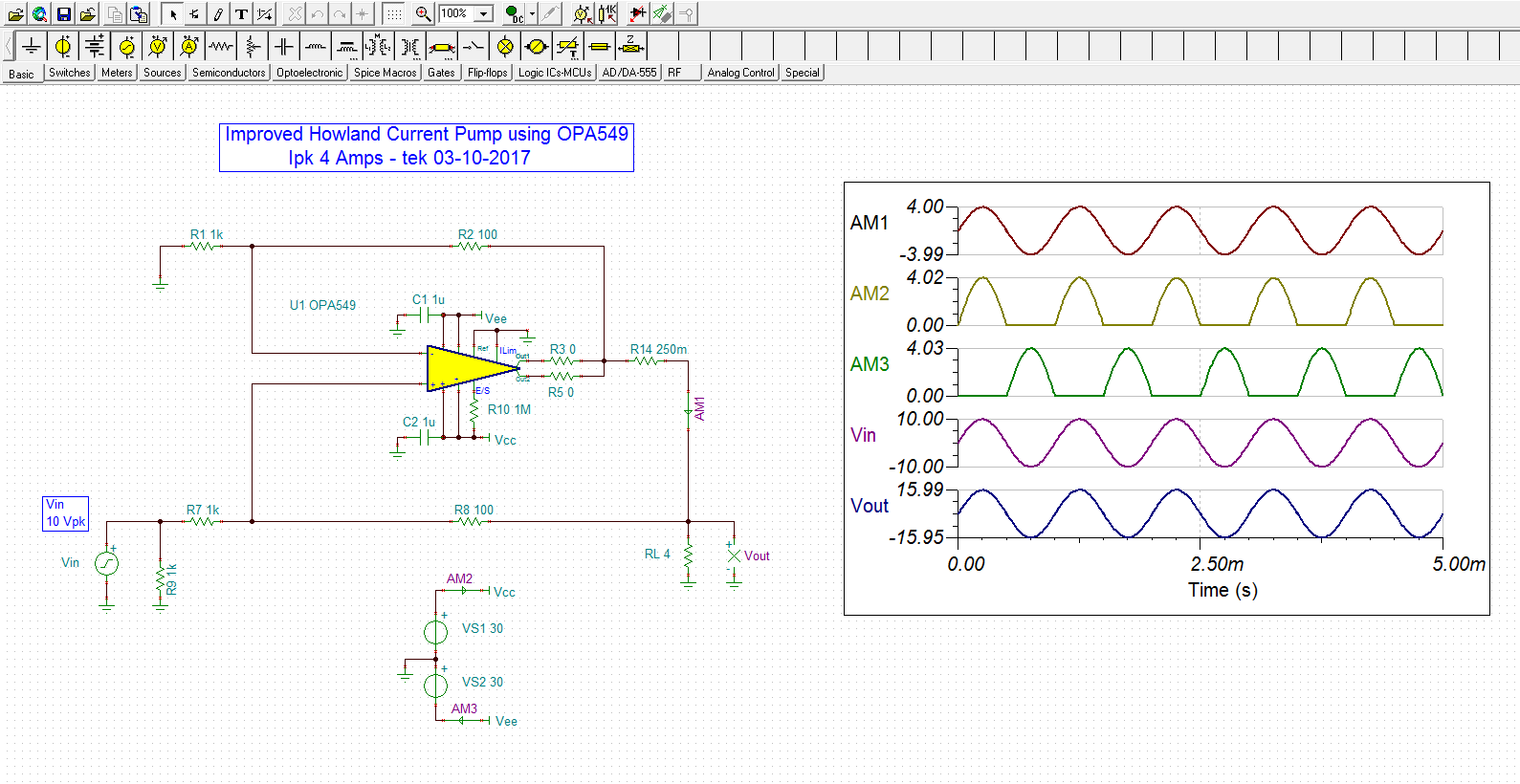
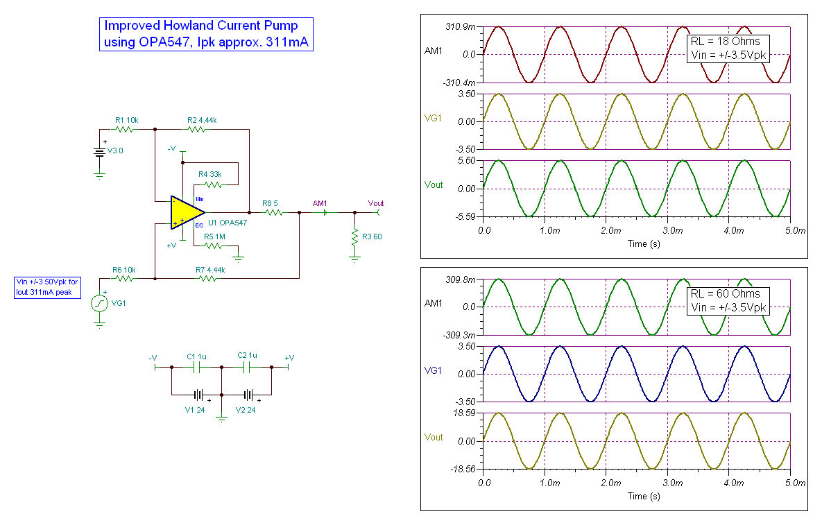
I want to design a constant AC current source of current variable upto 220mA rms.

The frequency of the current source will be from 400Hz to 1KHz. The impedance range is 18ohm to 60ohm.

Can somebody tell me whether Ti has a readymade solution for this?

If not please help me if you have any idea.


Thanks.

  • Hi Shihab,

    Is the AC input signal (400Hz-1kHz) referenced to ground, or will it vary about some DC input value? Is the output current sourced to ground, or some other potential? What supply levels do you have available?

    Since the current level is high (220mA) this application might be satisfied by an operational-amplifier, plus an external power device, or by a power operational-amplifier. We'll have to see the rest of your requirements.

    Regards, Thomas

    PA - Linear Applications Engineering


  • Hi Thomas,

    I think we have flexibility in AC signal since it is going to be designed by us. In my initial understanding, the AC input signal (400Hz-1kHz) is referenced to ground. Current should be sourced to ground. Supply level is not confirmed, it will be derived based on the current source requirement.

    Thanks,
    Shihab.

  • Hello Shibab,

    You mentioned that this requirement is for a AC constant current source with an adjustable current up to 220mA RMS. Since the current level changes with time then I must assume the peak current required is about 311mA - assuming a sine wave. You mention the current should be sourced to ground; does this mean it will be +/-311mA, sourced and sunk to ground?  If that is the case the output voltage will be swinging above and below ground (0V). Sorry I am having to ask for further clarification, but I want to clearly understand the requirements.

    What I am actually considering is a voltage-to-current converter.

    Regards, Thomas

  • Hi Thomas,

    Thank you for your reply.

    Peak current will be +/- 311mA. The output voltage will be swinging above  and below the ground.


    Thanks,

    Shihab.

  • Hello Shibab,

    I propose that an Improved Howland Current Pump could be applied in the AC current source application. The OPA547 is a power operational-amplifier that is well suited for the application and can easily deliver the +/-300mA peak current . Shown below is a schematic and corresponding TINA Spice simulation results for the proposed circuit. I didn't know the input voltage range, so I used +/-3.5Vpk as an example. The resistor values can be changed as needed to accommodate the correct input voltage range. Since you have some leeway with supply voltage I used +/-24V supplies. You will find that supplies levels of something on this order will be needed no matter what circuit configuration you decide to use.

    You mentioned that the load impedance range is 18 to 60-Ohms. Preferably that impedance is resistive in nature. The Improved Howland Current pump can become unstable with some reactive loads (like many operational-amplifier circuits). If the output load is reactive, then compensation may be required to stabilize things. I used a 5-Ohm sense resistor which helps add resistance in series with the output. Adding resistance in series with the output usually helps aid stability.

    I've attached a few Power Point slides from a current TI Tech Day session that provide much of the design information for the Improved Howland Current pump.

    Regards, Thomas

    PA - Linear Applications Engineering

    Improved Howland Current Pump.ppt
  • Thank you Thomas,

    The current stability required is 0.05% over 0 to 50degC. Can we achieve it if we use low temperature coefficient components and heat sink for the op-amp. I do not know how much accuracy is required. I read from one of the signal conditioning seminar of Texas Instruments that the accuracy of Howland current source will be 10 to 20%. Can we use a software calibration for improving the accuracy if required?


    Thanks,

    Shihab.

  • Hi Shibab,

    I did some rough calculations where I allowed the junction temperature to move 100 degrees and used the typical voltage offset and bias current drift values for the OPA547 circuit shown in the previous message. If the resistors are assumed to have zero TC, it does appear that 0.05% stability may be achievable at a specific current level. Of course the supplies and input level would have to be precise and stable to achieve this level of performance. Also, note that the actual current level does vary a little with the load resistance. The load (RL) information was cut off in the simulation plots that I previously posted. The upper plot was the 18-Ohm load and the current was +310.9/-310.4mA peak, while the lower plot was the 60-Ohm load and the current was +309.8/-309.3mA peak; about a 1mA, or a 0.3% change. I suspect that the closed-loop gain affects this and lower gain is better.

    One of the slides that I sent you demonstrated the criticality of precise resistor matching in the Improved Howland Current Pump circuit. It shows that with a 1% mismatch between the resistors results in an output current error on the order of 10%. Moving the resistor tolerance to 0.1% drives the output current error down to around 1%. Careful matching of the resistor values and their temperature coefficient should make that error level achievable.

    There are other voltage-to-current (V-I) converter topologies, but because your application requires a bipolar current output the Improved Howland Current Pump is a practical choice. Most of the V-I topologies I am familiar with have unipolar current output.

    Regards, Thomas

  • Hi

    I need to design AC currennt source of 1A curent.

    I am using OP548.

    It is working fine. But i need to implement open load protection. In open load condition i need to disable the output by taking feedback from output.

    Regards,

    Lolapu Gangaraju

  • Hello Lolapu,

    Are you using the ac implementation of the Improved Howland Current Pump that I recommended in that previous E2E thread to develop the ac current? If so, the output of the OPA548 used in the current pump will develop a higher and higher, peak to peak output voltage as the load resistance is increased. This will continue until the output swings as far is it can swing. With an open circuit the output will swing to the output stage extremes producing a square wave-like output waveform.

    The open-circuit voltage waveform could then be rectified, filtered and level shifted to produce a dc voltage which in turn be applied to the OPA548 Enable/ Shutdown pin. The idea is when the output current is at its normal 1A level, the dc level produced would not be high enough to trigger the amplifier's shut down. However, if the output did become an open circuit the developed voltage would be enough to send the amplifier into shutdown mode. Once in shutdown, the OPA548 output stage would be disabled and no current could be delivered. This would be maintained until the normal load condition was restored.

    Let me know what you think of this idea.

    Regards, Thomas

    PA - Linear Applications Engineering

  • Hi Thomas,

    Thanks for your reply

     I am not clear with the second idea that if output become open circuit the developed voltage would be enough to send the amplifier in to shutdown mode.

    That means OPA548 is having internal open load protection ?

    Other wise we need to use the open circuited developed voltage to Enable/shutdown pin.

    Is there any IC is available from TI to do this function?

    According to datasheet it is mentioned that if we want to shutdown the OPAMP we need to pull Enable / shutdown pin to -VEE voltage.

    If any implemented open load protection circuit is available can u please provide.


  • Hi Thomas,

    It is ok after rectifying the output voltage when inthe case of open circuit load operation the rectified DC output voltage is enough to send the amplifier in to shutdown mode.

    But without rectifying the Output voltage any alternate solution is available to protect from the Open load condition.

    Is there any IC is available from TI to do this function?

    According to datasheet it is mentioned that if we want to shutdown the OPAMP we need to pull Enable / shutdown pin to -VEE voltage.

    If any implemented open load protection circuit is available can u please provide.


    Thanks Regards,

    Lolapu Gangaraju

  • Lolapu,

    Please see my added comments.

    That means OPA548 is having internal open load protection ? An open load shouldn't be a problem for the OPA548 because no current is being demanded from the output stage. Thus, the internal power dissipation will be low and not a problem. No additional protection should be required.

    Other wise we need to use the open circuited developed voltage to Enable/shutdown pin. If for some reason an open circuit is a concern in you application, then this is the approach I would take.

    Is there any IC is available from TI to do this function? The enable/ shutdown function is provided when a customer has a requirement where they want to place the device in a low power, idle mode and shot down the amplifier output. I am not sure of what sort of additional IC you are thinking about.

    According to datasheet it is mentioned that if we want to shutdown the OPAMP we need to pull Enable / shutdown pin to -VEE voltage. To shut down the OPA548 output, the E/S pin needs to be biased with a voltage level of (V-) to (V-) + 0.8V, maximum.

    If any implemented open load protection circuit is available can u please provide. I do not know of any specific circuits. I do think the method I originally proposed will accomplish the task you have described. I suggest you download the free TINA-TI simulation software and use the OPA548 simulation model to try and develop the shut down control I described.

    Regards, Thomas

    PA - Linear Applications Engineering

  • Hi Thomas,

    Thank you for your suggestion i will download TINA-TI simulation software and simulate the open loop protection of OPA548.

    Thanks Regards,

    Lolapu Gangaraju

  • Dear Bruce,  

    My customer need a bipolar current source reference design (+/- 50mA output). Below is the requirement in detail. 

    the power supply of this circuit is +/-15V. the load is 50ohm resistor. V/I transfer ratio is 141.42V / A. customer want to transfer a +/-7.071V (50Hz) AC voltage signal to a +/-50mA (50Hz) AC current signal without distortion. overall accuracy should be below 0.2%.

    Could you help to promote a opamp and reference circuit for this requirement? By the way, customer is satisfied with the performance of TIPD102 reference design, but needs a bipolar output current source with high accuracy.

    Thank you very much.

  • Hi Wayne,

    My colleague, John Caldwell, is assisting you with your inquiry.

    By the way, Bruce retired this past year.

    Regards, Thomas

    PA - Linear Applications Engineering


  • Hello Thomas Kuehl,

    Is there a way to modify the same design with output current to be 4 Amps peak?

    Best Regards,
    Mubeen Haadi
  • Hello Mubeen,

    Yes, the Improved Howland Current Pump can be scaled to higher current levels. I have done so for a peak ac current of 4 Amperes as seen in the schematic shown below. I suggest using the OPA549 becuase of the potentially high power dissipation, especially if the power supply levels are increased to the highest levels. Such would be the case if the output voltage compliance range is maximized.

    I have attached my TINA Spice circuit for your evaluation.

    Regards, Thomas

    Precision Amplifiers Applications Engineering

    OPA549_Howland_4A_ac_01.TSC

  • Hi,

    Thank you for answering my question. Is it possible to have the 4 Amps Peak current independent of the load resistance?

    I have to force this current into primary winding coils of transformers of different dimensions. So the resistance is changing between 10 and 100 ohms.

    Best Regards,
    Mubeen Haadi.
  • Hello Mubeen,

    The Improved Howland Current Pump will provide a constant current for any resistance that allows the op amp output to operate within its linear output voltage compliance range. If you increase the load resistance above about 7 Ohms for the circuit I had shown, the peak voltage across the load resistor is 28 V. Note that the  op amp supplies were set to 30 V and that output can swing only so close to the supply rails. Four amperes peak through a 100 Ohm load is 400 V so the compliance issue becomes very evident with high resistance values. On the other end, the pump will provide 4 amps through a fraction of an ohm.

    Regards, Thomas

    Precision Amplifiers Applicaitons Engineering