This thread has been locked.

If you have a related question, please click the "Ask a related question" button in the top right corner. The newly created question will be automatically linked to this question.

AMC1100: Ground reference for 3 Phase Current sensing

Part Number: AMC1100
Other Parts Discussed in Thread: AMC3301, AMC0311R, AMC0100R, AMC0311D, TIDA-00366, TIDA-010025

Hi I was designing a 3 phase inverter(750VA). So I want to sense bus voltage and phase currents using AMC1100. Here is my reference circuit given by datasheet (I have modified it with red & blue marks). Can I use same power supply for VDDR, VDDY and VDDB? Shall I use seperate power supply for VDDA?  For AMC differential amplifier, is there GND need to tie VINN or will it work while left it floating? My intention is to make the circuit with minimum cost.
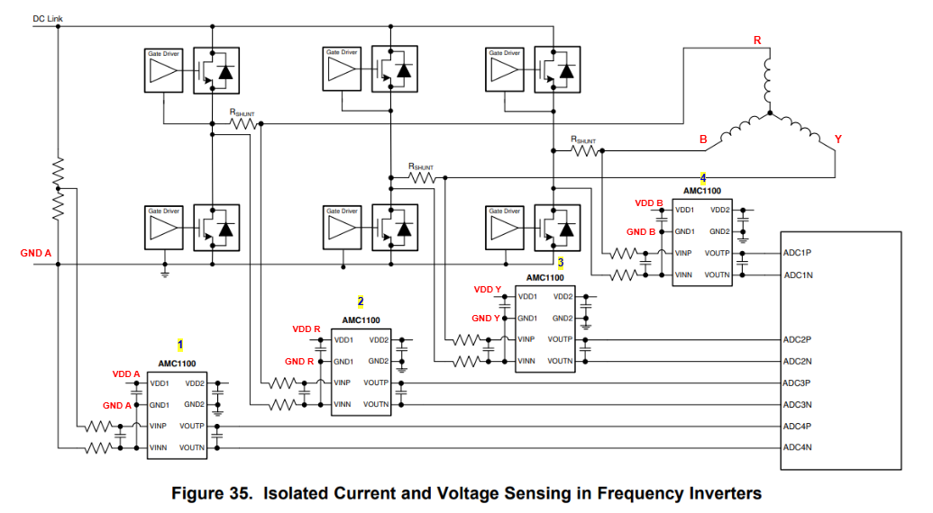
AMC1100.drawio.png

  • Hi Ijas,

    Our devices are only isolated between the left and right sides.  You will need separate power supply for each device since each device will be measuring off a different phase/voltage domain.  

    It may be possible to generate the supply from the gate driver supply on each phase similar to the diagram below:

    The other options would be to have some sort of discrete transformer to generate the supply or use one of our devices with integrated power such as the amc3301.

    For the question on the GND connection:  The GND1 needs to be connected to VINN in order to establish the common mode input voltage.

    Also, did you decide on using AMC1100?  The AMC1100 has a Basic level isolation rating.  Is that level of isolation all you require for you system?

    Thanks.

  • Thanks for your reply Saleh, 2kV isolation is enough for our application, so we have decided AMC1100. I need one more clarification, my gate drive is a bootstrap driver so that the connections done as per below: Three_Phase_Inverter_Driver_Circuit

    So How I can integrate AMC1100 current sensing circuit into this type of bootstrap driver and auxiliary supply?

  • Hi Ijas,

    Sorry for the delay, I was out of office last week.

    Can you attach the schematic as a PDF instead of through google drive.

    Thanks.

  • 3Phase_Inverter_ARDA.pdf.pdf

    Hi Saleh,

    Thanks for the update. No problem at all.
    I have attached the schematic as a PDF.

  • Hi Ijas,

    You would derive the power for the devices measuring the R, Y, and B currents from the VDDA/GNDA sets of each 2EDR8259X device for each respective phase.  

    For the voltage measurement you could use any one of the VDDB/GNDB sets to supply the device.

    Also, the amc1100 is an older part for current sensing.  We have some newer parts that might be of interest:

    The AMC0100R is the refresh for current sensing.  For voltage sensing, the AMC0311D (or AMC0311R) would probably be the best to use.

    We also have this design you can look at and reference: Three-phase inverter reference design for 200-480VAC drives (Rev. A).

    Thanks.

  • Thanks for your support, Saleh. I will proceed accordingly. Additionally, I found another TI reference design, TIDA-00366, which uses 2-channel isolated drivers for 3-phase PWM. However, I noticed that in these designs only the output current and the DC bus voltage are monitored. Why is the output line voltage not being sensed? How is the control logic implemented without measuring the output voltages? I searched extensively for the firmware/code for TIDA-00366 and TIDA-010025, but it has not been published anywhere.

  • Hi Ijas,

    I'm not sure on the reference design.  You should be able to get better answers from the team that made the reference design by making an E2E.  I'm sure they would have some SW available also.

    Thanks.