This thread has been locked.

If you have a related question, please click the "Ask a related question" button in the top right corner. The newly created question will be automatically linked to this question.

VFC32: Question about C1, C2, R1 calculation for VFC32.

Part Number: VFC32

Hello guys,

One of my customers uses VFC32 for their mass-production products.

Also they are going to use VFC32 for their next products too.
At this moment, they have the following questions to confirm if their understanding
about VFC32 is correct.

Could you please give me your answer top the follwoing questions?

Q1.
They use 20kohm for R1.
From Equation 1, VFS = 20kohm * 0.25mA = 5V.
They use 220pF for C1.
From Figure 2, Capacitor Value Selection,
fFS = (33000pF/(220pF + 30pF) = 132kHz
Are these equations correct?

Q2.
The measured value at 5V was 122kHz. There is a difference between the measured value and the calculated value. Is this difference mainly due to IC variation and RC variation? Or is the calculation formula incorrect?

Q3.
Does C2 affect the output frequency?
If there is no C2 value that matches the value shown in Figure 2, is it better to choose a larger value, or a smaller value?

Your reply would be much appreciated.

Best regards,
Kazuya.

  • Hi Nakai-san,

    Q1:
    The equation used is incorrect. 
    Since the target frequency is ~100kHz, I recommend changing R1 to be 40k ohm.
    Then fFS = (33000pF)/(220pF + 30pF) = 132kHz and full scale is vFS = 40k*0.25mA = 10V. 

    If the customer would like to use R1 = 20kohm. 
    Then the fFS = (66000pF)/(220pF + 30pF) = 264kHz and the full scale is vFS = 20k*0.25mA =5V. 

    Q2: 
    The value measured at 5V (122kHz) does not make sense to me, it should be around 264kHz as calculated in Q1 - I think this is not working because the target frequency is below 200kHz with R1 = 20k. I recommend changing the R1 to be 40kohm to produce a 25% duty cycle at full-scale frequency output.

    R1 should be a metal film resistor, C1 should be NP0 ceramic (make sure there is 2x voltage headroom). 

    Q3: 
    With R1 = 40k, C1 = 220pF, I recommend implementing a C2 which is larger or equal to 1nF. Polycarbonate capacitor is recommended for C2. 

    All the best,
    Carolina

  • Hi Carolina,

    Thank you very much for your reply.

    The customer want to set VFC32 for 5V VFS and 132kHz fFS.
    Is this function not realized by VFC32?

    Thank you again and best regards,
    Kazuya. 

  • Hi Nakai-san, 

    Please see the attached excel document with the calculated values for C1 and C2 for the customer use case. VFC32_equations.xlsx

    There is some expected variation as the standard capacitor values and calculated values will differ but the output frequency for C1 240pF and R1 20kohm should be 139kHz.

    C2 needs to be set at minimum 758pF in order to ensure the integrator output voltage stays within linear range. A standard value of 820pF was selected based on the calculations but this can be larger as Carolina mentioned. This will impact settling time and is calculated in the excel document as well. 

    Has the customer set up the schematic similar to Figure 1 in the datasheet? 

    Regards,
    Ashley

  • Hi Ashley, Carolina,

    Thank you very much for your strong supports and I'm sorry to be late my response.

    >Has the customer set up the schematic similar to Figure 1 in the datasheet?
      ->Yes. Their schematic is same as Figure 1 and each parts parameters are the follows.
         R1=20kohm
         C1=220pF
         C2=470pF
         +VCC=+12V
         -VCC=-12V

         And the actual frequency is about 122kHz when Vin=5V

    Their current questions are the follows.
    Could you please give me your answers?

    Q1.
    From Equation 1, VFS = 20kohm * 0.25mA = 5V.
    From Figure 2, Capacitor Value Selection, fFS = (33000pF/(220pF + 30pF) = 132kHz because C1=220pF
    Are these calculation correct?

    Q2.
    Their target frequency is around 132kHz. In this case, must R1 be 40kohm as Carolina said? Can 20kohm not be used?

    Q3.
    They use 470pF. Is this capacitor value too small?

    Your reply would be much appreciated.
    Thank you again and best regards,
    Kazuya.

  • Hi Kazuya-san, hope you are doing well.

    R1 can be set fundamentally by your input range. While R1 does influence your downstream frequency conversion equation, it is important to select this R1 value first as this is the primary means for scaling the input range.

    Since I assume we are using 5V, we can go with 20kOhm. 

    Q1:

    Spot on, this is all correct

    Q2: You can leverage the 20kOhm if you want to use a 5V input range. Per the above equation you mention, we calculate with a 20kOhm resistor.

    Q3:

    Yes, 470pF is too small. The nice calculator that Ashley shared has a minimum component value of ~760pF, with the next standard component value being  820pF.  Important to note, this C2 acts as the integrator capacitor for the triangle wave generator. Improperly sizing this component causes the slope of this generator to be so high that the resultant waveform has significant non-linearities. Even something like a 1nF would be perfectly fine here. If we size too small, we have linearity issues. If we size very large 10+nF, we will form a larger time constant on the integrator, causing more delay on the conversion. This is important to mention, as a larger C2 can sometimes be beneficial in scenarios where you do not need fast response. Larger C2 values will help reduce output ripple.

    Thanks,

    Jacob

  • Hi Jacob,

    Thank you very much for your reply.

    Could I ask you a few additional questions as the below?

    Q1.
    We can see 2 equations on the graph of Figure 2 as the follows.
    Equation 1: C1=33000pf/fFS(kHz) -30pF
    Equation 2: C1=66000pf/fFS(kHz) -30pF

    Please tell me how to use these formulas. Which formula is correct to use?
    When fFS(kHz) range is 1kHz~200kHz, is Equation 1 used?
    When fFS(kHz) range is 200kHz~500kHz, is Equation 2 used?

    Or
    When R1 is 40kohm, is Equation 1 used?
    When R1 is 20kohm, is Equation 2 used?

    Q2.
    I understood C2 value(470pF) is too small.
    You said it should be 820pF or more and should be less than 10nF.
    It is not good for C2 to be smaller than the value in the graph in Figure 2.
    However, is it okay if it is slightly larger than the value of the graph in Figure 2?

    Q3.
    Assuming there are no error of the external components,
    how much variation is there in the full-scale frequency of the graph in Figure 2?

    Your reply would be much appreciated.

    best regards,
    Kazuya.

  • Hey Kazuya-san

    Please tell me how to use these formulas. Which formula is correct to use?
    When fFS(kHz) range is 1kHz~200kHz, is Equation 1 used?
    When fFS(kHz) range is 200kHz~500kHz, is Equation 2 used?

    This is correct, equation 1 is for below 200kHz, and equation 2 is optimized for above 200kHz. 

    Understand, this sharp jump occurs due to setting the one shot timer duty cycle from 25% up to 50% when going from equation 1 to equation 2.  It has been determined that these equations offer the best linearity for the device. 

    Q2.
    I understood C2 value(470pF) is too small.
    You said it should be 820pF or more and should be less than 10nF.
    It is not good for C2 to be smaller than the value in the graph in Figure 2.
    However, is it okay if it is slightly larger than the value of the graph in Figure 2?

    Correct, 820pF is considered the smallest recommended capacitor size. Smaller than this value will cause issues for the integrator under certain scenarios. Larger is fine, though it may slow down the conversion time. Sometimes this slower conversion time is considered advantageous for noise and ripple reduction. 

    Q3.
    Assuming there are no error of the external components,
    how much variation is there in the full-scale frequency of the graph in Figure 2?

    This becomes a bit more complicated, but we have a section of the datasheet dedicated to this specification:

    First, we must separate into different terms, being FSR related and absolute error. 

    One of the most common sources of error is simple gain error. 

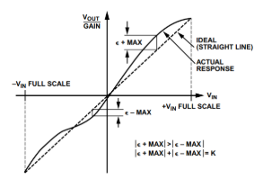
    Gain error refers to the difference between the ideal slope and the real slope. In this case, we specify the device to have a typical gain error of +-5%. For users who require better performance, Figure 3 shows how to adjust the part for better performance. Remember, this gain error will be a constant scaling factor to the transfer function. 

    Gain drift refers to how gain error changes over temperature, being specified in terms of PPM/C

    Linearity is related to gain error, but rather specifies how the GE will change over a certain span of frequency. This term can sometimes be relatively small in terms of error budget, though this depends on the frequency span, and if the user is calibrating out any error sources. For this device, the typical linearity error will be less than .05% of FSR. Here is a graph to show how we measure this parameter:

    Finally, we have DC errors similar to an op amp, where we Vos specified in mV, Vos drift specified in ppm of FSR/C, and PSRR specified in % of FSR / %. 

    These parameters will have a DC error independent of input frequency. Again, figure 3 can be used to calibrate out these errors if required. 

    All of this goes to say that the error budget depends on many factors including temperature, external component accuracy, and input frequency. The dominant error tends to be the gain error, though this can be greatly reduced if hardware/software calibration is used. 

    Please let me know if you have any additional questions. 

    Best,

    Jacob

  • Hi Jacob,

    Thank you very much for your polite and detail explanation.

    I could understand well.
    Could I ask you an additional question?

    Q.
    VFC32 is old device.
    Do you have any newer device which has similar function with VFC32?
    If you have it, I'd like to recommend it to the customer for their next products.

    Thank you again and best regards,
    Kazuya.

  • Hi Kazuya,

    No problem. You are correct, VFC32 is far from a modern device. Unfortunately, the V-F and F-V converter space has not seen significant investment in quite a while. 

    It is very valuable to receive feedback on these devices however, as there is likely still a market for devices like VFC32. Are there any key specs/features the customer is looking to leverage. Is there a reason the customer prefers a discrete device like VFC32 over a microcontroller based approach? 

    Thanks,

    Jacob

  • Hi Jacob,

    Thank you very much for your strong supports.

    Their product which uses VFC32 is an integrating current meter.
    Also the production volume is very low and they don't have any plan to design new product..

    Their design resource is not enough. So they keep to use same old design. 

    Thank you again and best regards,
    Kazuya.