This thread has been locked.

If you have a related question, please click the "Ask a related question" button in the top right corner. The newly created question will be automatically linked to this question.

INA238-Q1: INA238 with offset error

Part Number: INA238-Q1
Other Parts Discussed in Thread: INA238

We have a power distribution board with 40 power outputs. Each output can supply 3A, half of them are 28V the other half are 12V.

Example of one of the outputs:
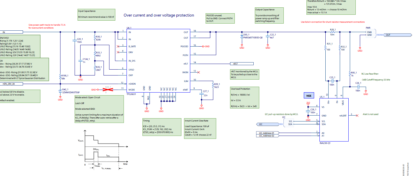
image.png

So far we have produced 20 of these power distribution boards. Each board tested thoroughly using an automated test setup.

Of the 800 output channels we found that 3 INA238s were measuring less current than being applied. 

At a current draw of 100 mA we were getting the reading of 79 mA. 

At a current draw of 3A we were getting a reading of 2.93 A.

We tried to explain this by calculating the tolerance of the circuit but could not explain the 21% error at 100 mA. 

We replaced all the passive components but this did not change the incorrect current reading.

Once we replaced the INA238 then we got readings of 100 mA +- 3mA.

The 21% error for the INA238 is definetly outside of its specification and at a rate of 3/800 this is a high failure rate.

Please could you assist us with this problem.

  • Hi Martin,

    I'd be happy to help.
    Just to confirm, is the diagram above showing the INA238 that's failing and are all 3 INA238's failing at the same location on the board?
    Can you confirm that none of the abs max specs are being violated?


    Best,
    Mallika Senthil

  • Hi Mallika,

    They do not fail in the same location. 

    Regarding the Abs Max Ratings:

    - The Max values are not being violated as there is sufficient transient protection.

    - The Min values are not being violated for the pins VAlert, VIO. Regarding VBus, Vin + and Vin- these have the filters as shown. 

    We will check if our assumption of the amount of inductive kickback in the system is correct. Other than increasing the RC filter what other options do we have in order to prevent negative spikes?

  • Hi Martin,

    We will check if our assumption of the amount of inductive kickback in the system is correct.

    This is a good start to debugging, please let me know what you find. Also, any scope shots you can provide will be appreciated.

    I'm not as concerned with the max values being violated as I am with the min values. Please note, RC filters may not be sufficient to suppress inductive kickbacks. Aside from filtering, you could also try Schottky diodes. 
    Please see the following application brief for reference: https://www.ti.com/lit/an/slyt862/slyt862.pdf

    Best,
    Mallika Senthil