This thread has been locked.

If you have a related question, please click the "Ask a related question" button in the top right corner. The newly created question will be automatically linked to this question.

PGA280: Vos vs. TEmperature

Part Number: PGA280
Other Parts Discussed in Thread: PGA281

Dear Team,

My customer is considering to use the PGA280, then they would like to have the following characteristics data.
a) Vos/℃ at each Gain setting
b) Ibias/℃ at each Gain setting
c) Ioffset/℃ at each Gain setting (Characteristics curve is OK)

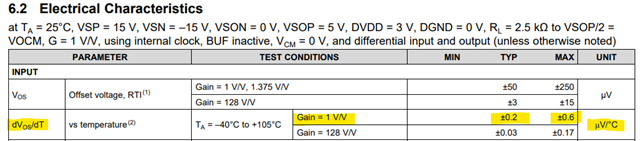
Although the typical values of G=1 and G=128 are listed in the datasheet, they would like to confirm the data for other gains.

Best Regards,

Koshi Ninomiya

  • Hi Ninomiya-san, 

    Do you know the target gains the customer will be using and if they require the SPI communication? This information could be easier to find on a newer device. 
    I looked through our device database and could not easily find what the customer is looking for - the PGA280 was released in 2009 and the characterization data available is limited. 

    All the best,
    Carolina 

  • Hi Carolina-san,

    The customer would like to know the following about the PGA280.

    For example, can you tell if there is a gain setting that is worse than when G=1? 

    Best Regards,

    Koshi Ninomiya

  • Hi Ninomiya-san, 

    The PGA280 and the PGA281 have the same core but are different in how the gain is set (pin programmable vs SPI). 

    The PGA281 datasheet shows an equation for the offset voltage and the offset voltage drift: 

    If I were to calculate the offset voltage drift for all gains using this equation for the PGA281, I would get the following results: 

    Offset voltage vs temp, RTI (uV/C)
    Gain  Typ (+) Typ (-) Max (+) Max (-)
    0.125 1.470 -1.470 3.770 -3.770
    0.172 1.077 -1.077 2.786 -2.786
    0.25 0.750 -0.750 1.970 -1.970
    0.344 0.553 -0.553 1.478 -1.478
    0.5 0.390 -0.390 1.070 -1.070
    0.688 0.292 -0.292 0.824 -0.824
    1 0.210 -0.210 0.620 -0.620
    1.375 0.161 -0.161 0.497 -0.497
    2 0.120 -0.120 0.395 -0.395
    2.75 0.095 -0.095 0.334 -0.334
    4 0.075 -0.075 0.283 -0.283
    5.5 0.063 -0.063 0.252 -0.252
    8 0.053 -0.053 0.226 -0.226
    11 0.046 -0.046 0.211 -0.211
    16 0.041 -0.041 0.198 -0.198
    22 0.038 -0.038 0.190 -0.190
    32 0.036 -0.036 0.184 -0.184
    44 0.034 -0.034 0.180 -0.180
    64 0.033 -0.033 0.177 -0.177
    88 0.032 -0.032 0.175 -0.175
    128 0.031 -0.031 0.174 -0.174
    176 0.031 -0.031 0.173 -0.173

    As you can see the offset voltage drift is higher for lower gains and matches (in a more conservative way) what is specified in the PGA280 datasheet. 

    This trend however is shown in RTI (or referred to input, which means it measured at the output and divided by the gain of the device). When the gain is an attenuation (less than 1) as is the case of the PGA280/281 - it can be deceiving. 

    I have done the same calculation but referring to the output so you can see how much of the error is seen at the output: 

    RTO
    Gain  Typ (+) Typ (-) Max (+) Max (-)
    0.125 0.184 -0.184 0.471 -0.471
    0.172 0.185 -0.185 0.479 -0.479
    0.25 0.188 -0.188 0.493 -0.493
    0.344 0.190 -0.190 0.508 -0.508
    0.5 0.195 -0.195 0.535 -0.535
    0.688 0.201 -0.201 0.567 -0.567
    1 0.210 -0.210 0.620 -0.620
    1.375 0.221 -0.221 0.684 -0.684
    2 0.240 -0.240 0.790 -0.790
    2.75 0.263 -0.263 0.918 -0.918
    4 0.300 -0.300 1.130 -1.130
    5.5 0.345 -0.345 1.385 -1.385
    8 0.420 -0.420 1.810 -1.810
    11 0.510 -0.510 2.320 -2.320
    16 0.660 -0.660 3.170 -3.170
    22 0.840 -0.840 4.190 -4.190
    32 1.140 -1.140 5.890 -5.890
    44 1.500 -1.500 7.930 -7.930
    64 2.100 -2.100 11.330 -11.330
    88 2.820 -2.820 15.410 -15.410
    128 4.020 -4.020 22.210 -22.210
    176 5.460 -5.460 30.370 -30.370

    Now a new trend emerges that shows that as the gain gets bigger, so does the error. 

    Here is the excel I used to make all these calculations: offset_drift_calculations.xlsx

    All the best,
    Carolina