This thread has been locked.

If you have a related question, please click the "Ask a related question" button in the top right corner. The newly created question will be automatically linked to this question.

INA199: Brownout

Part Number: INA199

Hi Team, 

May I have your help to check below questions? The application is E-cigar and we notice no ouput failure case, customer observe abnormal impedance between IN+-. 

1. What are the common failure modes you encounter for abnormal impedance in the IN+ and IN- pins?
2. Does the IC have any requirements for the power-on sequence of each pin?
3. If the device frequently enters Brownout Recovery mode, will it damage the device? 
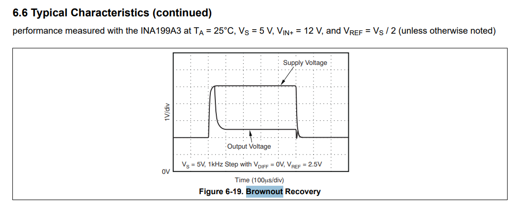
image.png

  • Hello, 

    Thank you for your post. 

    1. We have ESD diodes on the inputs that will turn on when the common mode voltage dips below 300mV or 100mV, depending on the variant. If these ESD diodes were triggered, then this could cause large input current to the IN+ and IN- pins as a result of device damage. 
    2. Yes, the REF input and negative common mode limitation must be adhered to during power on sequence. If these are powered on before the supply voltage then this can damage the device. 
    3. It should not damage the device if the ABS Max ratings table is followed and there is no negative common mode voltage on the pins below 300mV and no reference input until the supply is in the recommended range. 

    I hope this helps, 

    Joe

  • Thank you Joe! 

    Regarding questions 2, 

    if the IN+ and IN- pins are continuously powered (uA/mA level), and then the Vcc and ref are repeatedly powered on and off, would this situation cause damage to the chip? (The power-on voltage is within the specified range)

  • Hello Kailun, 

    Assuming the correct power on sequence is adhered to (VS-->VREF), when the power is cycled, I would ensure that the current is limited on the inputs to 5mA. This is not the current through the shunt but a clamp to ensure input bias current does not exceed that when the device is powered off.

    It is described in this post: (3) INA186-Q1: Short to GND at IN+, IN- - Amplifiers forum - Amplifiers - TI E2E support forums

    This should protect the pins. 

    I hope this helps, 

    Joe