This thread has been locked.

If you have a related question, please click the "Ask a related question" button in the top right corner. The newly created question will be automatically linked to this question.

INA241B: OpAmp Buffer for REF1 and REF2

Part Number: INA241B

Hello, 

We're designing with the INA241B and had a quesiton about using an opamp to buffer that input.

It doesn't seem like this is necessary, but i found another post discussing better accuracy with the opamp.

Could you please commnet on the best configuration & errors we could anticipate?

Thank you, Keith

  • Dear Keith,
    Thanks for the question and using the E2E forum. Due to the U.S. holiday, we are currently out of the office. Someone will reply when we return starting 4/6.

  • Hi Keith, 

    Thank you for your post. 

    The short answer: you don't need a buffer on the signal inputs (IN+/IN-), but you almost certainly do need one on the REF pins if you're using a resistor divider to set a custom reference voltage. That's likely what the post you found was referring to.

    Signal Inputs (IN+/IN-): No Buffer Needed

    The INA241B is designed to connect directly to your shunt resistor [1]. Its 120 dB minimum CMRR [1] handles the high common-mode voltage natively, and no buffering is required or recommended on the sensing inputs. One important caution: avoid adding RC filters at the inputs. Component mismatches from tolerances and temperature drift can degrade CMRR from ~100 dB down to 40–60 dB. If you need filtering, place it at the output instead [3].

    REF Pins: Buffer Required for Resistor Dividers

    This is where the accuracy problem lives. The REF pins are not high-impedance inputs — they draw approximately 35 µA of bias current through an internal ~606 kΩ resistance tied to an internal bias voltage [2]. If you're driving them from a resistor divider, that current will load down the divider and pull your reference voltage away from the intended value.

    This isn't theoretical. A real-world case confirmed a 13 mV drop on a 0.613 V reference (Thevenin impedance of ~8.33 kΩ) — a ~2% error before the INA241B even processes a signal [2]. TI explicitly states that using an unbuffered resistor divider for single-ended output is not recommended because internal impedance shifts adversely affect device performance specifications [4].

    The fix: Use an op-amp configured as a voltage follower between your resistor divider and the REF1/REF2 pins, exactly as shown in Figure 7-9 of the INA241B datasheet [1]. The op-amp's low output impedance absorbs the REF pin bias current without disturbing the reference voltage.

    When you don't need a buffer: If your REF pins connect directly to VS, GND, or a dedicated low-impedance precision reference IC, no buffer is needed — those sources can sink the 35 µA without issue [5].

    Error Budget to Anticipate

    Even with a properly buffered reference, account for the INA241B's inherent error sources:

    Error Source

    Typical

    Maximum

    Gain error (25°C)

    ±0.02%

    ±0.1%

    Gain error (full temp)

    ±0.15%

    Gain error drift

    ±0.2 ppm/°C

    ±5 ppm/°C

    Input offset voltage

    ±25 µV

    ±150 µV

    Offset drift

    ±100 nV/°C

    ±500 nV/°C

    Source: INA241B datasheet [1]

    Without a buffered reference, REF pin loading adds a fixed offset error on top of all of the above — and that offset scales with the Thevenin impedance of your divider, making it difficult to calibrate out.

    Recommended Configuration Summary

    Scenario

    Buffer Needed?

    REF pins → VS or GND

    X No

    REF pins → precision reference IC

    X No

    REF pins → resistor divider (single-ended output)

    White check mark Yes — voltage follower

    IN+/IN- → shunt resistor

    X No

    Input RC filter

    Warning️ Avoid — use output filter instead

    A few things would help sharpen this further: Are you measuring unidirectional or bidirectional current (this determines whether you need a mid-supply reference at all)? What's your target reference voltage and supply rail? And do you have a precision reference IC available, or are you planning to use a divider? If you're going the divider route, the op-amp selection matters too — you'll want rail-to-rail output capability and low offset to avoid introducing new errors at the reference node.

    Citations

    1. INA241B Datasheet (SBOSA30D)
    2. E2E Forum: INA241B Loading of Reference Voltage Pin
    3. E2E Forum: INA180 Input and Output Filters
    4. INA241B Datasheet (SBOSA31D), p.21
    5. E2E Forum: INA241B REF1 and REF2 Resistor Values

    I hope this helps, 

    Joe

  • Hello,

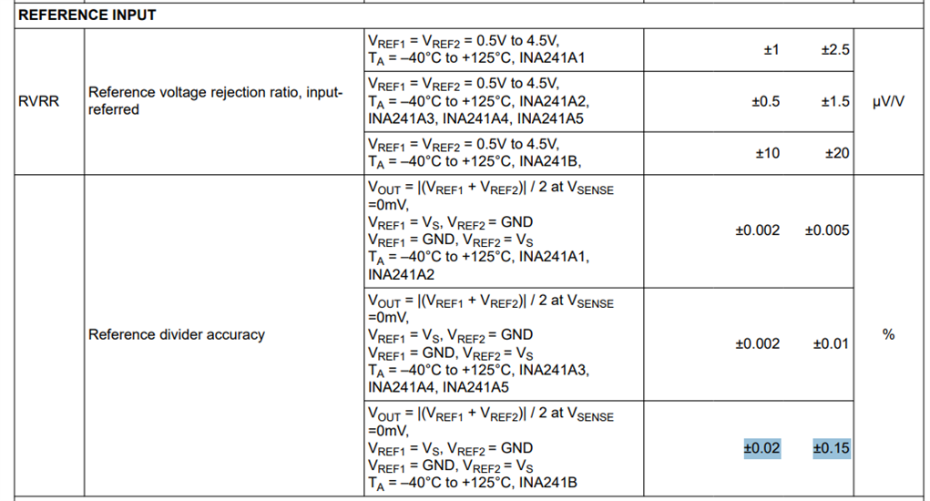
    Thank you for the information.   Would you agree that we can use the Internal REF1 and REF2 buffer without adding an opamp if 1.65V works in our system and the accuracy of 0.15%.

    Thank you, Keith

  • Hello Keith, 

    Thank you for the follow-up. 

    I would say that you can use the INA241 in this configuration if your error targets are 0.15% over temperature.

    I would try to reduce all other errors in your system with calibration to try to stay below the 0.15% error.

    I would specifically perform a one-time calibration on the 0A input current output condition (VS/2 ±0.15% in your case) to remove 25C offset and also ensure that you have a good bypass capacitor scheme. 

    I hope this helps, 

    Joe