Part Number: INA296A
Hi Experts,
Would like to ask assistance from product expert point of view.
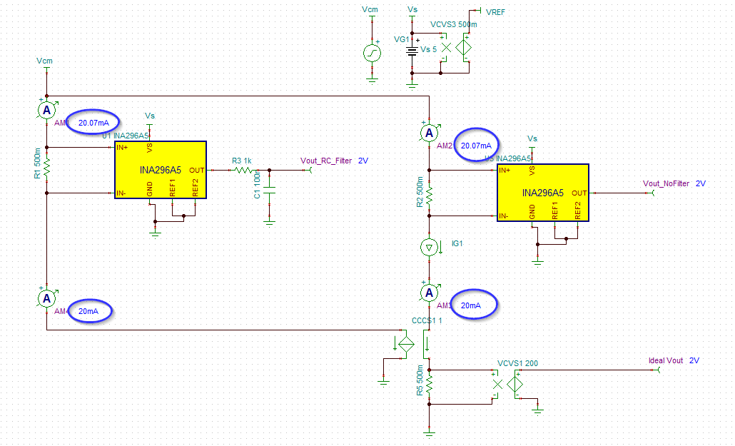
This technical inquiry addresses the application of the INA296A current sense amplifier in a low-side configuration with a 0.5-ohm shunt, measuring a 100 kHz PWM current from 0 to 20 mA while aiming for a 50–100 µA error target.
[1] What is the input offset current (I_os) or the difference in input bias current (I_b) between the inverting and non-inverting inputs for this device?
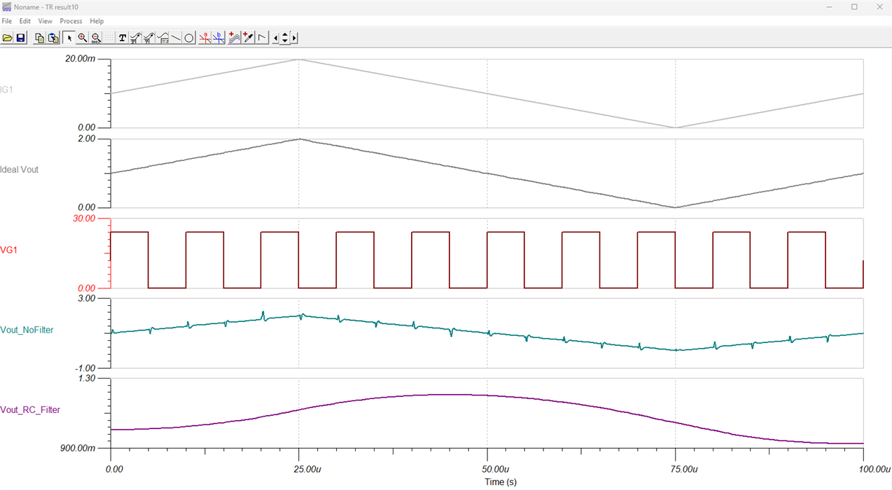
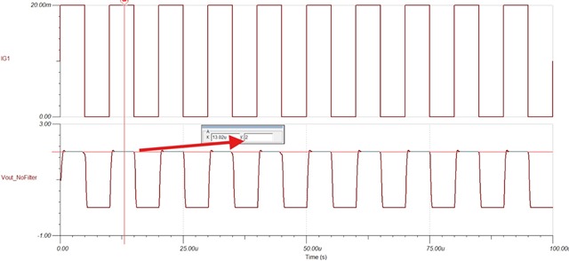
[2] Can a design utilizing the 200 V/V gain variant (INA296A5) successfully meet the accuracy target of 50–100 µA under these operational conditions?
[3] Can an RC low-pass filter be connected directly to the OUT pin to extract the average current value given the 1 nF capacitive load limitation, and will utilizing a capacitance below 1 nF alongside a larger resistor satisfy the minimum 1 kHz cutoff frequency requirement?
Thank you.
Regards,
Archie A.