This thread has been locked.

If you have a related question, please click the "Ask a related question" button in the top right corner. The newly created question will be automatically linked to this question.

Negative Input Current for LOG102

Other Parts Discussed in Thread: OPA140, OPA637, OPA627

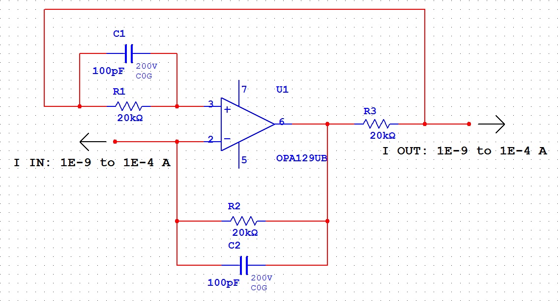
I am trying to measure a negative input current with a LOG102 amp. The data sheet specifies several options, however, they specify input currents of 10 nA to 1mA, and I would like to be able to measure currents of 1 nA to 100 uA. The LOG102 is floating at a voltage which varies from 0 V - 10 V, and has +/-15 V supply. Currently I am using an OPA129 to invert the current, however, at low currents, the behavior is not ideal.

  • This is the present configuration. The OPA129 was selected for its low bias current, 100 fA max, however, a bias current of 1 pA would be acceptable. If the output of the op-amp was controlled better, then greater precision could be achieved in the current inversion.

  • Henry,

    I believe the problem with your circuit is the offset voltage of the OPA129. A 1mV offset voltage causes 1mV to be impressed on R3 with zero input current. Thus, zero input current will produce an output current of 50nA. The issue can be mitigated somewhat by increasing the Value of R2 and R3. This will proportionally reduce the error due to offset voltage. Your full-scale input current of 100uA produces a maximum output voltage of 2V on U1. You could reduce the error by 5x by using 100k resistors for a max output voltage of 10V. This, however, still would not be accurate enough to cover your full range of input current.

    With this circuit, you need both very low input bias current and low offset voltage. You might want to consider using the OPA128 or OPA111. These devices have lower offset voltage, but more importantly, they have offset voltage trim pins. This could allow you to adjust the offset voltage. Is this a possible solution?

    Regards, Bruce.

  • Bruce,

    I can't use larger resistors, as the entire setup is floating from 0 to 10 V, and the supply is +/- 15 V. If I went to 100k, then at 10 V and 100 uA the amp would have to produce a total of 20 V! (In general, at higher voltages, we expect to see higher currents.)

    The offset voltage tip may be exactly what we need. I'll look into it and see if it solves the problem.

    Thank you,

    Henry

  • Bruce,

    The two amps you suggested are listed as not recommended for new design, but from there, I found four others that might fit the bill, OPA124, OPA129, OPA140, and OPA637. It seems to me it would be more important to emphasize offset voltage, based on these calculations, where VOUT is the voltage at the output current and VO is the voltage at the output of the op-amp:

    V+ = VOUT - IIB*R1

    V- = V+ +/- VIO

    VO = V- + (IIN + IIB)*R2

    IOUT = (VO - VOUT)/R3

    IOUT = (R2/R3)*IIN +/- VIO/R3 + (R1/R3)*IIB - (R2/R3)*IIB

    So if we let R1 = R2, the last two terms cancel, and the equation becomes:

    IOUT = (R2/R3)*IIN +/- VIO/R3

    And thus by minimizing VIO, maximizing R3, while maintaining R1 = R2 and the desired gain, we can minimize the error. Based on this analysis, I choose the OPA140, for its low input offset voltage of 30 uV, giving 1.5 nA output for zero input current.

    Does this analysis make sense? Do you agree with it?

    Thank you,

    Henry

  • Henry,

    You are correct that offset voltage is the dominant error, by far, if you must use 20k resistors. For this reason, I was selecting op amps that allow trimming of offset voltage. The spec on the OPA140 is 30mV, typical, 120uV maximum. If this will suffice, it is a good choice.

    The OPA637 should not be used as it is not stable in G=1. The companion device, OPA627, is stable in G=1. It also has pretty low offset voltage and it has trim pins in the DIP or SO-8 package versions. It's probably the best choice if you want to trim offset voltage.

    R1 seems unnecessary in your circuit due to the very low input bias current error on a 20k resistor. Here is a link to a blog on that point:

    http://e2e.ti.com/blogs_/b/thesignal/archive/2012/04/11/input-bias-current-cancelation-resistors-do-you-really-need-them.aspx

    Regards, Bruce.