This thread has been locked.

If you have a related question, please click the "Ask a related question" button in the top right corner. The newly created question will be automatically linked to this question.

Summing amplifier using OPA134 is unstable

Other Parts Discussed in Thread: OPA4134

Hi everyone!

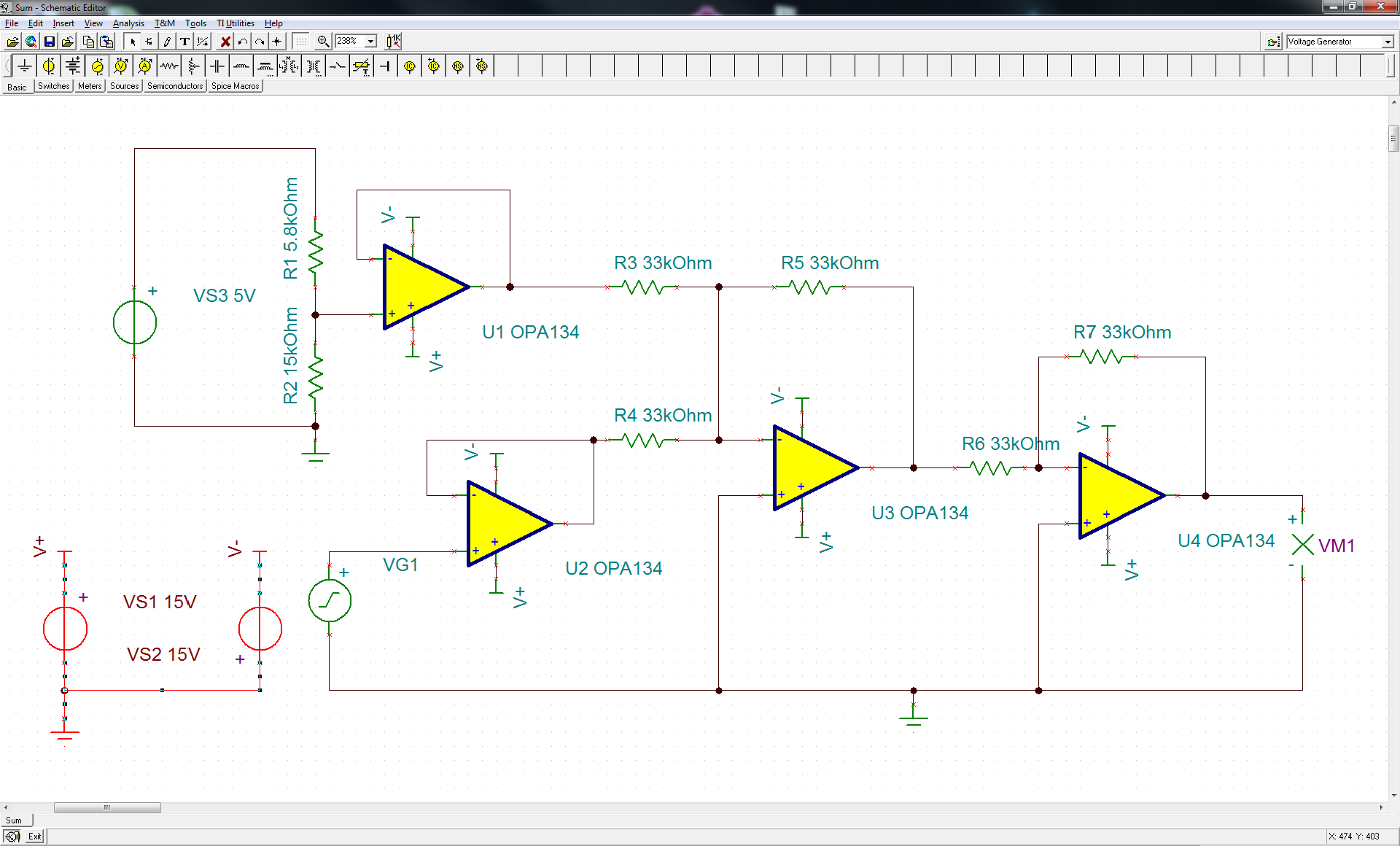
So for some reason I need to add an offset of 3.6 V to a sinusoidal signal. I have set up a circuit according to this schematic:

I know that there are probably easier ways to do this but it should work and give the following results (red is output, green excitation):

For some reason however the output of the summing amplifier is a 1 MHz signal which I do not understand. Can anyone here explain this behavior?

Some additional information:

  • the IC used is an OPA4134 in a SO package
  • the schematic is actually only a small part of a larger circuit, that's why the voltage buffers are there
  • the excitation in the actual circuit is the output of a XR2206 function generator
  • there are vias under the IC, could that be a problem (stray capacitance)?
  • V+ and V- are bypassed vs. GND with 100nF capacitors on the actual board

I would appreciate every piece of advice or idea you can give me!

  • Hi Simon,

    You are correct there are easier ways to accomplish this but if you're okay with this design we can get it working.  The 1MHz output signal is likely an oscillation due the feedback+input resistance interacting with the input capacitance of the amplifier.  The simplest way to solve this issue will be to reduce the value of the feedback and input caapcitor by an order of magnitude (3.3k instead of 33k).  Another option without modifying the current values would be to place a capacitor across the feedback resistor, try a 22pF to start.  I'm not sure what bandwidth you're trying to achieve but the capacitor across the feedback will limit the closed-loop bandwidth to 1/(2*pi*Rf*Cf).  Therefore if bandwidth is an issue try to find the smallest capacitor value that works to stabilize your circuit without limiting your bandwidth to an unacceptable level.

    One of my colleagues wrote a few very nice blog topics which you can read here:
    http://e2e.ti.com/blogs_/b/thesignal/archive/2012/05/23/why-op-amps-oscillate-an-intuitive-look-at-two-frequent-causes.aspx

    http://e2e.ti.com/blogs_/b/thesignal/archive/2012/05/30/taming-the-oscillating-op-amp.aspx

    Hope this helps,
    Collin Wells
    Precision Linear Applications

  • Thank you Collin, this looks exactly like my problem. I will try this today, though I don't think I have such a small capacitor at hand. I want to operate the circuit at 10 to 15 kHz but the smallest capacitor available right now is 10 nF limiting the bandwith to up to 3 kHz if I have understood you correctly. Still I'll see if this helps to suppress the oscillation and will get smaller caps as soon as possible.

    Just to make sure I got this right from the blog posts (because I want to learn something): The input capacitance and the feedback resistor form a lowpass that introduces a feedback delay on the input. If the delay is sufficiently large resonance will occur and the circuit becomes unstable. The delay can be reduced by reducing the value of the resistor or by buffering the feedback with a capacitor. Is that about right?

  • Wow, Collin, you got it completely right!

    First I tried adding the capacitor which stopped the oscillation but limited the bandwith so I removed it and reduced the resistor values by an order of magnitude to 3k3 Ohms and now it's working exactly like it is supposed to! Thank you so much!

  • Hello Simon,

    I'm glad this worked for you.

    As for your understanding of the theory, you're pretty close.  Basically the input capacitor forms a delay with the input resistor and you need to balance that effect by placing a capacitor across the feedback resistor.  Without going into the real theory regarding the poles/zeroes AOL, 1/Beta, and AOL*B (loop-gain) the basic problem is that the input capacitance is in parallel with the input resistance.  Therefore over frequency the input resistance of the circuit changes.  Since closed-loop gain in a non-inverting OPA circuit is 1 + Rf / Ri  if the input resistance (Ri) changes over frequency then the gain changes over frequency as well.  To stop this from causing an issue we need to try to balance the reduction in input resistance by reducing the feedback resistance over frequency as well and the capacitor accomplishes this effect.

    Hope this helps,
    Collin Wells
    Precision Linear Applications