This thread has been locked.

If you have a related question, please click the "Ask a related question" button in the top right corner. The newly created question will be automatically linked to this question.

OPA277 oscillation

Other Parts Discussed in Thread: OPA277, OP07, OPA376

Hi,

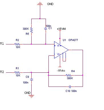
Following a former post on OPA277 instability due to output capacitance, here is a schematic for a low pass filter done with this op-amp.

Using this op-amp OPA277 seems to bring instability on the output voltage and op-amp is warmed. By reducing the feedback capacitor to 20nF, instabilty is reduced, op-amp is not warmed, but not enough to stop instability and overshoot.

Voltage gain of the low pass filter is big (G = 300) and cutoff frequency is low.

A previous post on OPA277 oscillation reveals that overshoot on output voltage seems to be induced by the output capacitor which value is too high (capacitor value higher than 1nF) with this op-amp.

Nevertheless, if I want to keep same gain and Fc and also, avoid an overshoot on the output voltage by a low output capacitance, resistors value on the feedback network have to be very high (higher than 20Meg) and I believe that transfer function is modified due to resistor value which become closer to open loop gain of the amplifier.

With an OP07 amplifier, this low pass filter is OK.

thx for your help


  • See attached detailed analysis. 

    Summary is:

    1) Original Circuit loads output of OPA277 with 50nF of capacitance. A%0nF interacts with open loop Zo of 40 ohms and forms a second pole in the modified Aol.  High frequency 1/Beta is close to 6dB and results in 40dB/decade rate of closure indicating marginal stability.  Closed loop peaking in transfer function shows peaking also indicative of marginal stability. 

    2) New Cricuit gives symmetrical transfer functions for both inputs and is very stable since there is no direct capacitor load on the output of OPA277. 


    Diff Amp Low Pass.ppt
  • Thank you for your reply and detailed analysis.

    I don't find the way you apply your guide for modeling complex Z0 for op-amps . Especialy for Z0 of OPA277. Not the same procedure as in the guide isn't it ? You set L and C to 1T instead of using a R/L pole to determine Z0 for your example with OPA376 (i.e. Step 5 - final Z0 Test circuits Results).

    I would have do the same study as yours with op-amp OP07 to find out OP07 internal Z0 and to check if Fcp2 formed by Z0 and Output capacitance.

    Is TINA a better simulator than SPICE ? or complementary taking into account real op-amp characteristics ?

    Do we have the same conclusion (as to know : no capa on inverting input) if values of resistors or capacitors are slightly different ? typo error on input resistor (1/10) since closed loop gain has to be close to 300.

    Thx


  • With reference to testing Zo on Op Amp SPICE macro-model there is always more than one engineering way to solve a problem.  Either way is okay for your application.

    TINA is based on SPICE.  TINA uses SPICE based macro-models.

    Op Amp macro-models are only as good as the macro-modeler. For about the past 5 years TI has gone to great lengths to ensure Op Amp macro-models match typical performance shown in the data sheet. 

    Also I ran a couple of quick sanity simulations with lower value of input resistor to 1k on your circuit and our trick on the input resistor cap isolation will work fine.  TINA SPICE also has a pre-built macro-model for OP07.  In general I think most any op amp with a capacitor in the feedback and a capacitor on the input will need a close look for stability based on what we presented above.