This thread has been locked.

If you have a related question, please click the "Ask a related question" button in the top right corner. The newly created question will be automatically linked to this question.

Capacitor noise in Transimpedance Amplifier

Other Parts Discussed in Thread: LMH6629, TINA-TI, OPA847

Hi TI engineers,

Currently I am designing a low noise high speed TIA, and I am reading one of the TI documents -- "Transimpedance Considerations for High-Speed Amplifiers", in the part of noise considerations, I encountered an unfamiliar term in the input referred noise current.

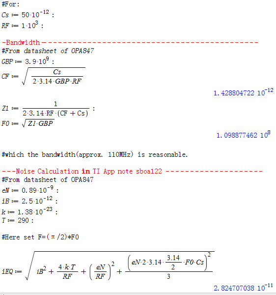
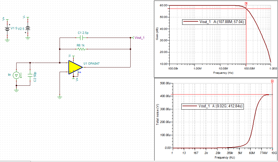
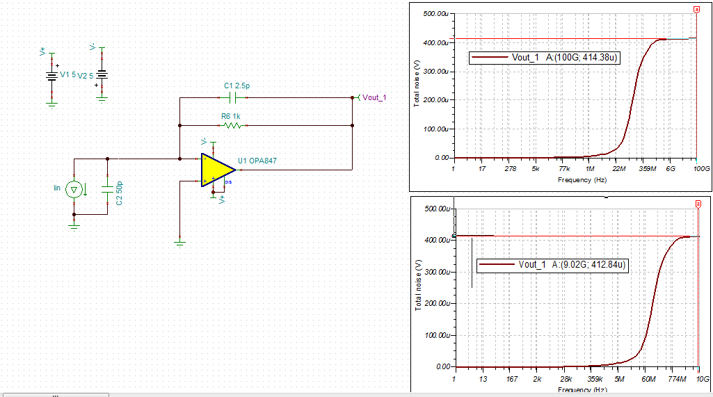
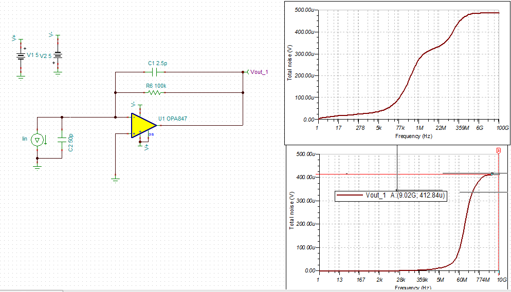
The noise analysis circuit is as following:

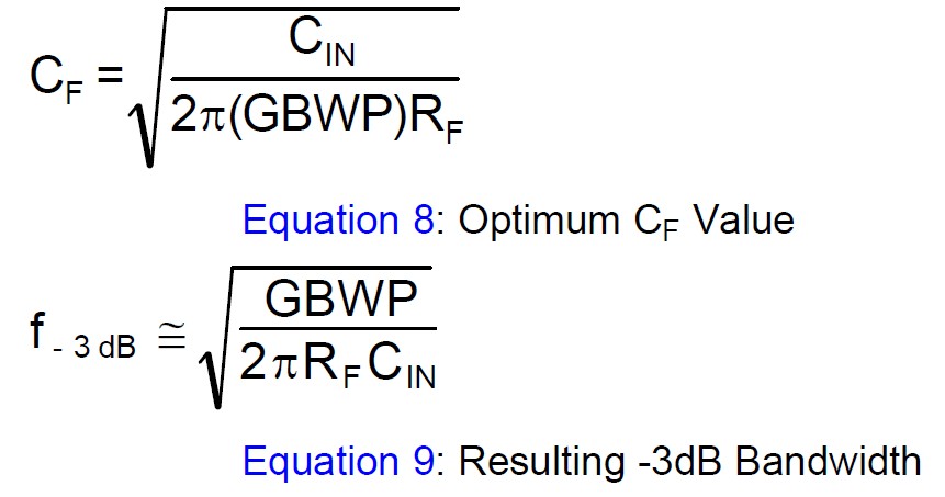
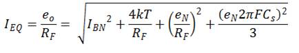
The unfamiliar term is tagged out with red square in the following:

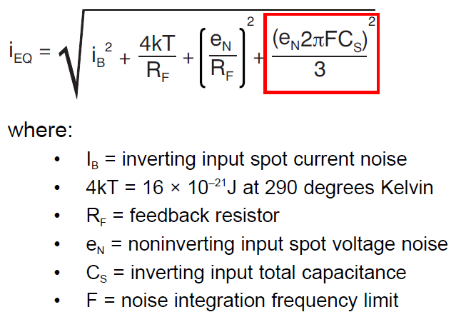
It seems to me that it is a noise current on the source capacitance, however, why there would be a "\sqrt{3}" in the demoninator? Could anyone explain this to me?

Apart from that, in this noise analysis, no feedback capacitor is used. If a feedback capacitor is added parallel to the feedback resistor, how would the noise current be in this case?

Thank you very much!

Best regards,

Zhao

  • Hello Zhao,

    The noise term you have highlighted is related to the additional noise because of Noise Gain increase (which starts at "Z1" in Figure 2 of that application note) acting on eN. I'm pretty sure that this analysis assumes that CF is chosen to optimize BW (Q=0.707 or Butterworth response), even though Figure 4 does not show CF explicitly. The proper value of CF for optimum response is shown in Equation 12.

    Regards,

    Hooman

  • Correction!

    Contrary to what I said earlier, "CF optimum" expression is not in Equation 12! I've shown it below for reference (from the LMH6629 datasheet):

    Regards,

    Hooman

  • Zhao,

    The 3 comes from the integration of F2, which results in F3/3. I’ve shown the analysis below.

    http://e2e.ti.com/cfs-file.ashx/__key/communityserver-discussions-components-files/10/5123.Capacitor-Noise-Posted-by-Luke-Lapointe.docx

    To solve for eo, use superposition

    Combine all the noise sources:

    Solve for IEQ:

    Which matches equation 13 in the app note.

    Additionally, to add to Hooman's post, assuming that the feedback RC pole lies on the open loop curve (to maximize transimpedance gain), its affect on the noise analysis will be negligible. In reality there will be a small region where it shapes the noise, but for practical purposes you can assume that the bandwidth of the amplifier rolls off the noise at the equivalent noise bandwidth:


    Keep in mind, this should give a pretty good estimate of the noise, but it is just a model and the actual results will be close but not exact. Other factors like board parasitics will play a role as well and you will likely have check/modify to get the best response on the bench.

    Regards,
    Luke Lapointe
    High Speed Amplifiers

  • Hi Luke!

    the analysis of the formula is lost.(the links not available??) Could you provide the derivation once more? thanks!

    Br,

    Jason

  • Hi Jason,

    I also saw that the derivation was missing a few minutes ago! But, it is up again for me.

    Please retry.

    I've attached it here anyway in case it is missing:

    5123.Capacitor Noise Posted by Luke Lapointe.docx

    Regards,

    Hooman

  • Hi Hooman,

    I still could not see the missing pics, but thanks for the helpful attachment.

    I tried to calculate with this formula, but the result seems not "reasonable" somehow, I could not figure out what is wrong within my calculation. Here is the calculation file:

    the input noise is only 28pA. 

    I tried in TINA-TI too, in order to get the same bandwidth, i increased the feedback cap a little larger to 2.5pF.

    As you could see in the snapshot, the output noise in around 400uV, which with the 1Kohm feedback resistor,

    the input -referred current noise should be 400nA, why there is almost one decade difference between these two? even with the noise bandwidth 2*F0 instead of (pi/2)*F0, the difference is still big.

    Thanks!

    BR,

    Jason

  • Hi Jason,

    A 1k resistor noise density will be 4nV/RtHz at the device output. However, taken over a bandwidth of 9GHz! (your TINA-TI cursor), that would corresond to 476uV_RMS:

    en_out= 4nV/RtHz x SQRT (9GHz * pi()/2 )= 476uV_RMS


    Not too far from the 400uV you are getting with TINA-TI.


    Regards,

    Hooman

  • Hi Hooman,

    thanks for the quick reply, but your argument could not convince me for now.  The reason is:

    1.let's do another simulation with frequency up to 100GHz, the result is as following:

    you can see the noise does not go up actually.

    2.if we increase the resistor up to 100k, the result:

    again, the total output noise does not go up too much.

    my opinion is, the output noise is also related to the transfer function of the system. I tried to derive the transfer functions for each noise source at the output. I would try to give out the derivation tomorrow(German time). And also I think that is why we need to specify equivalent noise bandwidth for integration instead of using the transfer function(it would be too tedious, in my opinion).

    BR,

    Jason

  • Hi Jason,

    Couple of points:

    1. The IEQ expression, which is average input referred noise current density, should be multiplied by RF and by the SQRT (BW_EQUIVALENT) to become output RMS noise voltage (for comparison with TINA-TI plots you have sent)

    2. The IEQ expression has an upper frequency limit where it still holds and beyond which is no longer valid

    The expression for IEQ, below, is an average noise density expression with units of A/RtHz (not Amperes). To get the RMS output noise (equivalent to your TINA-TI) simulation, IEQ should be multiplied by the bandwidth which this expression holds and also multiplied by RF (1kohm).

    With RF=1k, your calculation seems to show a bandwidth of 109.8MHz (F0) and IEQ= 28pA:

    Vout_noise_RMS_simple= 28pA x SQRT(109.8MHz) x 1kohm = 292uV_RMS

    To be more exact, the equivalent bandwidth would actually be pi()/2 times higher because of a single pole roll-off characteristic you would expect:

    Vout_noise_RMS_exact= 28pA x SQRT(109.8MHz* pi()/2) x 1kohm = 366uV_RMS

    You cannot use 10GHz in these calculations as the IEQ expression will not be valid at frequencies much above 109MHz. For one, the amplifier seizes to behave normally (because of the lack of loop gain at high frequency) and all ideal amplifier assumptions (i.e. zero differential voltage, no input current, etc.) break down. That's why your calculations should be limited to 110MHz maximum or lower, and not further.

    Hope my points are clear.

    Regards,

    Hooman

  • Hi Hooman,

    now I see, I careless took the spectral noise as rms noise. I used another way, which instead of considering the op amp is ideal at the beginning, and set an equivalent noise bandwidth to integrate the total noise, I consider the noise source as independent source, and derive the transfer functions for each source WITH the open loop gain Aol(s) of the opamp inside. Then to integrate (noise density)*(transfer function) from 0 to inf. This would be a finite value because the transfer functions would be considered as LF filter and the equivalent noise density here is white. The advantage of this is, I don't need to care about the integration limit, regardless of what kind of filter. The disadvantage is also obvious, people could not solve this by hand.

    E.g. , the noise gain of op amp voltage noise, in Luke's derivation, is 1+Rf/Cs, and the full noise gain if Aol is considered, would be: (Zs+ZF)*Aol / (Aol*Zs+Zs+ZF). As we could see, when the Aol is very large, the result is the same.

    when input Cap =50pF

    simulation - 500.47uV (when the feedback cap set to 2.5p with the same bandwidth 109MHz,, the noise is 413uV, the reason why i do this would be explained in the second question)

    Method (sboa122) - 371uV 

    Method (mine) - 362uV 

    When I increase the input cap to 350pF,

    simulation - 671uV 

    Method (sboa122) - 603uV 

    Method (mine) - 576uV 

    I don't know why my results are smaller even that I have only used ‘one pole dominant“ assumption(as you could see in the expression op amp voltage noise above), If I introduced a second pole, I think the result would be even smaller?

    However, I still have a question about the 3db bandwidth.

    with the same parameter, say, OPA847(set GBP=3.9GHz, Aol=90dB, first dominant pole=10^5kHz), RF=1k, According to the formula before, CF is 1.43pF, F0 is 109MHz, But when I input the same value in TINA, the output experiences a large overshoot, thus the bandwidth is certainly larger. If overshoot omitted, the 3db point is around 145MHz. I also use the transfer function to calculate with the same value(RF,CF,GBP,Aol..), the result is 130MHz.

    My question is, why with the same CF, the bandwidth should not be same? or if we consider the input capacitance of the op amp, the simulation should even have a lower BW. And I think this is why the noise estimation would be lower than the simulation, because of different BW.

    I hope I explained my question clear enough. Thanks.

    BR,

    Jason

  • Hi Jason,

    One thing I like to say is that if you are trying to match the theoretical to the TINA-TI simulation, you have to keep in mind that the TINA-TI model is only an approximation / macromodel. You cannot expect a 100% match.

    BTW, the diode capacitance and the input capacitance (both CM and diff mode) should be considered together for your analysis. This is in fact what is looking at your RF. If your photodiode is 50pF, then there will be a small impact (more impact with lower photodiode capacitance).


    Regards,

    Hooman