- Ask a related questionWhat is a related question?A related question is a question created from another question. When the related question is created, it will be automatically linked to the original question.

Hi,
I'm using a circuit which accepts a differential input through simple non inverting buffers and applies it to a Differential to Single ended converter(D2S) stage to obtain a single ended output. The schematic with the non inverting buffer section zoomed in is attached below.

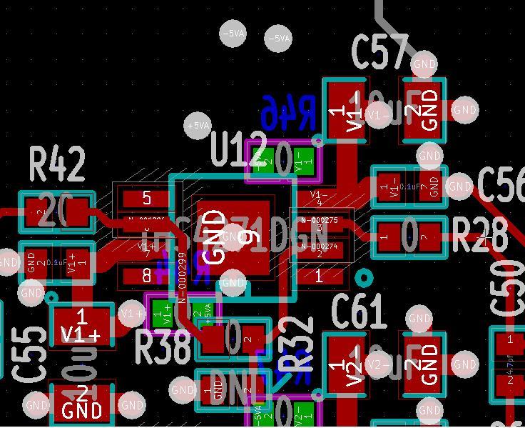
The issue observed is that, the idle channel output, ie the output of the circuit with the inputs shorted to ground is observed to be very noisy. When checked with a digitizer with an inherent integrated idle channel noise of around -69dB, the integrated noise at the D2S circuit output comes to around -40dB. I'm sorry I couldn't attach an FFT plot to this mail, but it is seen that the noise floor itself goes real high. I could isolate the source of the noise and find that it was coming right at the output of the non inverting buffer. This is when the feedback resistor for the non inverting buffers were set as 0 ohms. When I checked with 250 ohms feedback resistors, it was observed that the output got totally clean, and I could measure some -68dB idle channel noise at the D2S output, very near to the digitizers inherent idle channel noise. I cannot really understand why the 0 ohms resistors caused the noise floor to worsen so much. I read in the datasheet that for unity gain configurations there are chances this op amp can show instability if the feedback resistance is 0 ohms, but that is supposed to happen at pretty high frequencies, ie around100MHz I believe. I'm doubting if it is due to some extra parasitic capacitance coming in the feedback path.. Can you please provide some insight into why 0 ohm resistance causes the noise floor to worsen for the non inverting buffer so much compared to say a 250 ohms resistance.A snap shot of the layout of the non inverting buffer section is given below: The hatched lines indicate cut out areas in the power and ground planes.