This thread has been locked.

If you have a related question, please click the "Ask a related question" button in the top right corner. The newly created question will be automatically linked to this question.

Power Amp Tab

Other Parts Discussed in Thread: OPA549, TINA-TI

The OPA549 data sheet says the tab is connected to the V- supply, but should not be used to carry current. My ohm meter sees more than 10 Megohms resistance between the tab and V- of OPA549S. So, will there be any harm in connecting the Tab to a Voltage mid-way between the V+ and V- supplies? (It would be convenient to connect it to Chassis Ground which can vary somewhat around the mid-point. )

  • Hi Dennis,

    The OPA549 integrated circuit uses reversed-biased junctions to maintain transistor-to-transistor isolation. The die substrate which the transistors are built upon needs to be biased at the most negative supply level (V-) to assure the transistors remain isolation from one another. Biasing the substrate at a more positive level increases the risk of degraded electrical performance and the possibility of a catastrophic bias condition.

    Regards, Thomas

    PA  - Linear Applications Engineering

  • Thanks!  This will help!

    Dennis

  • One more question:

    Since I will be isolating the tab from the chassis, must I connect the tab to the V- supply? 

    Or is there an adequate internal bias in spite of the fact that my Ohm meter doesn't see it?


    Regards,

    Dennis

  • Hi Dennis,

    It is preferable to connect V- to the tab. Doing so hardwires the OPA549 V- pin and the tab. That shorts out any capacitance created between the back side of the IC die and the tab. That alleviates any concern about any effects the stray back capacitance might have on the ac performances. This is probably a minor, secondary effect, but something you won't have to be concerned about if eliminated.

    Regards, Thomas

    PA - Linear Applications Engineering


  • Thomas,

    Thank you very much!  This is helping solve a problem.  Now I have another issue which I believe to be unrelated.

    I am using (2) OPA549s to drive a bridge-tied-load.  The Supply Voltage is 41 Volts.  The current is limited to 5.1A.

    The load is a 2.4mH load with 4 Ohms resistance.  When I drive with a sine wave at high frequencies (e.g. 600 Hz the load requires enough current that I can put significant current into the load. My problem is that when the output Voltage of one amplifier reaches about 25 V (pk-pk) it folds the peaks and troughs over.  (The other amplifier does not.)

    Three amplifiers assemblies I've tested exhibit the same phenomenon, and it's always the same amplifier which folds its peaks and troughs.

    Any ideas?  (I have a PDF schematic and scope capture cued up in case those will help.)

    Regards, Dennis

  • Send a detailed schematic for review along with input signal amplitude, wave shape and frequency.  Also give a description of the power supplies being used?  Lab supplies, switchers, etc? With this information we can probably diagnose the problem.

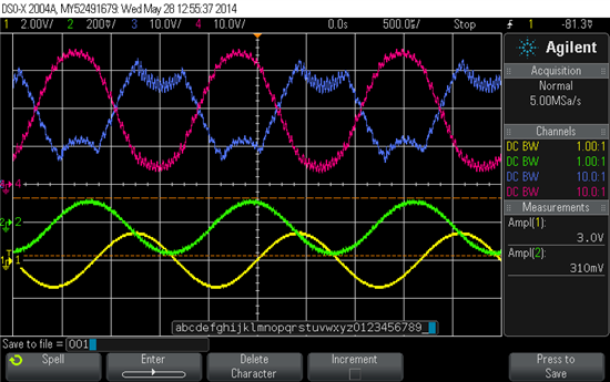
  • The red and blue traces are the differential outputs from the two power op amps (OPA549) driving the load.  These are U8 and U9 on the attached schematic.  For some reason the output of one op amp (U8) folds its peaks and troughs over when the output Voltage exceeds about 25 Vp-p.  Three amplifier units exhibit the same response – the same amplifier folds. 

    The yellow trace is the sinusoidal 600 Hz 3.0V p-p input.  If I decrease the input amplitude so that each output is less than about 20V p-p, the outputs are then sinusoidal. The green trace shows the displacement of the voice coil type motor being driven.  The green trace is inverted. 

    The load is a voice coil.  L = 2.4 mH, R = 4.5 Ohms.

    A DC/DC converter supplies the power.  Its output is 41V.  Its protection circuit is shown forst.  Its power  comes from a large 12V truck battery.

    Thank you very much (!) for looking into my problem.  It is an important issue to two companies.  Please ask for any other information you desire.

  • The following corrections were made to teh PCBs but not to the Servo schematic I uploaded:.  It is the first schematic of 3)

    U2 pin 3 is not connected to VGND but rather to 1/2 VGND.  (10K-10K resistive divider from VGND) so the output will swing about VGND.  Region C3

    Change C28 and C29 to 27pF to reduce feedback delay.  Region B5.

    Pull J4-1 to Signal Gnd with 10K to reduce noise pick-up.  (J4 is used only for testing)

    A diode between pins 6 and 9 of U8 (and U9) prevents pin 9 from being pulled lower than VGND.

  • One other change to the circuit has been implemented. Based upon the advice in this thread, R29 was changed from 10K to 1 Ohm to keep the chassis close to Pwr ground, and thus keep the Power Op Amps U8 and U9 properly biased inside.

  • We did not get the schematics that you may have tried to upload.  pdf format if you can.

  • Servo Amp PCB Schematic in .PDF  (updated according to today's notes) follows.

    2234.Servo_Amp_PCB_304A_Old_OrCAD.pdf

    DC/DC converter schematic (PDF) follows:

    3582.DC-DC_CONVERTER_106_.pdf

    [ I can not tell whether the PDF files will appear on your end.  This time I used "Insert Image" whereas I copied and pasted last time.  If there is a better way to get .PDF images to you, please let me know.]

  • Got the drawings now.  Will analyze and reply with results later today.

  • There is some unique feedback around the OPA549 I have not seen used in over 32 years of working with power amps.  I would prefer to expedite the solution to this problem.  I am familiar with power op amps and bridge tied loads as I focused on just power op amps at Apex Microtechnology for 5 years. Can you give me a contact number I can call you?

    If not I need the following:

    What command voltage are you putting out of U2A pin 1 and based on that what do you want across the bridge tied load?  Is your design goal to have current control through the motor or just voltage control across it?

  • Tim,

    The design was by a respected Russian engineer who has designed quite a few amplifiers.  I was involved, but he was the designer.  He started from an application note at http://reanimator-h.narod.ru/bridge.htm    Unfortunatelly I don't read Russian.  His first prototype used the OP2541AM.  I suggested the OPA549s as a less expensive replacement.


    His company gave up the project and I inherited it a few weeks ago.  I have 30 complete amplifiers (DC/DC converters, Servo Amps, Housings, Cable sets) and two potential customers who are ready for me to install multiple units.  But I confess to not understanding the amplifier well.  I've had some amplifiers working "pretty well" for over a year and have demonstrated to several potential customers.  So the company for whom I consulted made 30 units.  Now when I try to install other "identical" amps in the machine, I sometimes get a huge offset and the machine is inoperable.  My bench test (with the same servovalve but not the entire machine) shows the amplifiers to be very similar.


    The input at J1 is 0 to +/- 40mA across R1.  So, from U10-8 I expect about +/- 4V. The output is expected to be about 0 to +/- 5A.  And yes, the desired output is current.  Current drives a voice-coil style linear servovalve spool.  The spool has a displacement sensor, and its output is connected to J5 and allows us to control Spool position.  It is part of a servo loop which has additional "external" loops. 

    The quiescent Voltage at U2-1 is expected to be 1/2 the supply Voltage.  The supply is about 40.7V so the output at U2-1 is expected to swing from 20.35V.  (It is a single supply amplifier.)  So the Voltage at U2-1 is expected to be approximately 20.35V +/- 5V. That assumes sinusoidal operation, but there is a lot of distortion in the machine, and the Voltage will go higher to partially counter-act the distortion and to speed the machine up.

    The machine's normal operating bandwidth is roughly 1 to 400Hz.  Going over 150Hz is unusual, but our purpose is to expand the usable bandwidth of the machine.  The machine is a seismic vibrator and is used for oil and gas exploration.

    My phone number is (405) 747-4691.  Thanks very much!

  • We stand no hope of diagnosing this problem unless the circuit architecture is understood and built in a SPICE simulator so we can quickly see when and where the op amp specifications are being violated, which is what I believe is causing the problem. Attached is an English translation of the Russian Web Article. We use the free TINA_TI SPICE simulator with a download link below. I will look into unraveling this.  It smacks of a possible marginal design where compo9nent tolerances are catching up to you.  Let's see what we can discover.  I would encourage you in parallel to build this up and begin analysis to see if input common mode voltage, output saturation, or loop stability is being violated. I will spend some time to see if I can decipher what was done and build it in TINA-TI SPICE.

    http://www.ti.com/tool/tina-ti


    Bridge Power Amp.doc
  • Attached is a TINA-TI SPICE schematic of your circuit I am using for deeper analysis.  Consider downloading the free TINA-TI simulator so we can discuss issue in a common simulator.  I will call you when I get in tomorrow to discuss eliminating know variables until we can figure out root cause of what is happening.

    OPA549 Motor Drive mid ref.TSC
  • I have downloaded Tina9-TI.  Now I shall:

    1.  Look over the schematic.

    2.  Set up an amplifier and servovalve (load) on a lab bench

    3.  Establish a "standard" input and verify Voltages at various nodes.

  • Tim,

    The coil inductance changes with frequency, according to the factory.  (I didn't know coils could do that.)

    Their graph of inductance vs. frequency is attached in .PDF format.

    7268.Yuken coil Inductance Oct12.pdf

     The information I gave you regarding gain is incorrect.  Though there is a "Current" output, it is so noisy that I have not tried to measure the gain using it.  At one point, I started to filter that signal, but the designer thought the noise was a real representation of what the amplifiers were doing, so I have not yet filtered it.  I could do so externally though.

    I have not taken the discipline of calculating the gain.  I suppose that if I went through that process, I'd have a clear understnding of the amplifier.

    In spite of what I just said, I have been adjusting the gain of all amplifiers to be equal in this way.     I drive the amplifier with a 1V p;-p sine wave at 100 Hz. and then reduce the "Internal loop gain" pot R24 until the (~30KHz) noise on the outputs is less than 5V p-p.  Then I adjust the "External Loop Gain" pot (R3) to get a 500 mV p-p sine wave at the monitor connector J5 pin 3.

    This is unclear to me, but I keep thinking that slightly less than half the current fed back to the inverting input of each power amplifier is positive feedback, and that this contributes to the noise, and that some kind of unbalance which I don't understand sometimes allows the positive feedback to dominate and (a) cause a lot of offset, preventing operation, and (b) causes the peak and trough fold-over, and causes a lot of noise.


    Another thought is that the reduction in the coil's inductance with frequency is somehow allowing high frequency noise to have too much affect.  There is unfortunately a lot of high frequency noise in a typical seismic vibrator's control system.  I once did a spectrum analysis and found a broad-band patch of noise between 5 and 10KHz with a few single-frequency spikes at various frequencies - notably 4KHz.

    I am sharing these thoughts in case they help clarify something to you.  I realize that they may just be chaff in the wind.

    Thanks very much for your help!

    Dennis