This thread has been locked.
If you have a related question, please click the "Ask a related question" button in the top right corner. The newly created question will be automatically linked to this question.
Dear,
I have a problem while amplifying the signal of a load cell by using a INA125P (integrato)
I am not able to achieve a defined value under a certain limit. Here following some examples:
If a insert the Arduino ADV value read without load =0, the error is spread on all measurements. If I detract it I still experience no detection untill a certain limit.
By using a 200N load cell I get a value (related to the gain set), of about 20 ADC without load, which finally correspond to a initial reading threshold of about 0,7 - 0,8 N.
Normally we use 3000 N load cell. The threshold moves consequently thus preventing low loads detection that yet become significant ( about 10%).
I also cannot perform load cell calibration, as normally it is applied by linking the ADC value to 0 load and the FS to the relevant value. This because 0 value is underneath the threshold.
By resuming, it is like the load cell zero was under the threshold amplifier reading.
So, If I could move the zero value to a slightly higher tension, I should have solved the problem. But I do not know how to get this done.
To simplify:
If I have not load reading under the reading threshold I will never be able to calibrate these.
Let's consider the example of a Kitchen balance that starts to weigh right over the 100 gr. value ( it would not visualize 99 gr, yet it would visualize 101 gr). If I place a 80 gr plate ( but of course I do not know it before...) and then I want to weigh 500 sugar gr, how can I detract the plate weight?
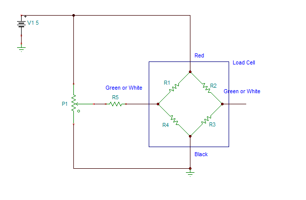
Enclosed Scheme picture
Thanks,
Sergio
Sergio,
All bridge type sensors have some amount of offset without any force applied due to slight mismatches in the internal resistances of the sensor. You can see this by applying a voltage to the bridge sensor and measuring the no-load voltage output from the sensor with a voltmeter. My, now retired, colleague Bruce Trump and I addressed this issue in this thead: http://e2e.ti.com/support/amplifiers/precision_amplifiers/f/14/p/223084/785468.aspx#785468
Essentially you can apply a voltage to null the bridge offset at zero load without losing ADC range.
Dear John,
first of all thanks a lot for Yr help.
Fantastic, this will resolve my problem!!! ...but I'm not a technican so I don't understand how to connect it in practice;, can You please draw how plug the variable resistor to load cell and INA125
My best,
Sergio
Increasing the voltage at IAREF will prevent the output of the INA125 from saturating at the negative rail. The compromise is that you will be losing output range. For example, if V(IAREF) = 1V, then the INA125 will output voltages from 1V to VCC, if this compromise is acceptable in your system then it is a reasonable solution.
You are right ...I didn't thought!
Sorry but I cannot understand how to connect the variable resistor to a load cell output...I've to connect the two output wires to Ina125 6-7 input pins ...so, where I can put the resistor ???
I've tried to put the resistor between the wire and the Ina125's pin but it's not working at all.
Can You please teach me how can I do, thanks a lot !
Dear John, I'm really in troubles with this :-(
Can You please let me know how can I connect the resistor to load cell output.
Thanks again,
Sergio
Sergio,
The connection diagram in my post is correct, one input of the INA125 would connect to the right of R5, the other input would connect to the other load cell output. R5 is absolutely essential for this schematic to work.
Hello Enrique,
The INA125P is the standard 16-pin DIP package. Even though I'm unfamiliar with ISIS, I imagine you could find a part in the library that uses the same package and modify it so it has the pinout for the INA125P.
I hope this helps.