This thread has been locked.

If you have a related question, please click the "Ask a related question" button in the top right corner. The newly created question will be automatically linked to this question.

INA125: Problem with gain INA125P

Part Number: INA125

Hi Guys!

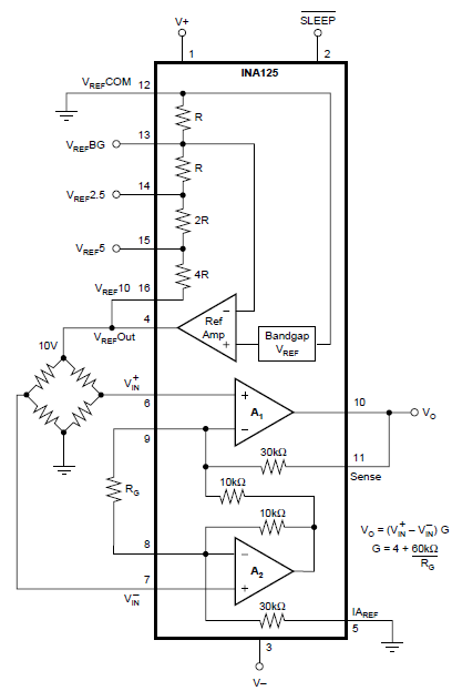
I'm connecting a HBM load Cell (C9C) with my INA125P as it come in datasheet,Altought I feed the INA125P with +/- 10V and the Load Cell with +5V.

My load Cell have a sensivility of 1mV/V and when the load cell hasn't  load, my difference between Vin (+) and Vin(-) is 0.0001V.My problem is when my Rg is 68 Ohms,my Vo is different to te teoric value.This problem is the same with other value of Rg.

Why my  value of Vo is different if my resistances are 1% tolerance?

Thanks.


  • Changing Rg resistor changes the gain, which directly affect the gain error and non-linearity - see below.

    Using 1% tolerance resistor will cause the gain to be up to +/-1% in error.   Therefore, Gain=100 may be instead 99 or 101, which directly effects your Vout.

  • Hello! thanks for your response.

    When I saw datasheet,I saw the tolerances,but my datas are illogicall,for example:

    Rg= 216 ohms

    G= 281.77

    Vi(+)-Vi(-) = 0.0001 V

    Vo Theoric= 0.02817 V

    Vo Real= 0.0302 V

    This problem is the same for All resistors less than 10K.What is the problem?

    Thanks for your help.

  • user5079828,

    Have you calibrated out the system error?  If not, you must factor in tolerances of the part itself like the input offset voltage.  Since you're applying 100uV input signal while the maximum input offset of INA125 is as much as +/-500uV, what you see at the output is Vout=Gain*(Vin+Vos) = 281.77*(100uV+/-500uV), thus Vout may be anywhere between 0.169062V and -0.112710V.  Therefore, 0.0302V output voltage you read is well within these limits and what you see means only that your input offset is 7.2uV; what you need to do is to short the inputs and first determine the total error by looking at the output, and then account for the error in your calculations.

  • Hi friend!

    I just tried both inputs to grounds and my Vo is 0.0279V with a G=604.

    When I connect a differential Input of 0.0001V,my Vo is 0.0786 V so my Voffset is 3.01 Exp(-5)

    Why Vo with inputs to grounds is different if I put a differential input of 0.0001 value?

  • Assuming you have an exact gain of 604, with the inputs grounded, your input offset would be closer to Vos=0.0279/604=46.2uV then 30.1uV.

    But in your measurement you do not account for the gain error; thus you first need to determine the actual gain and only then use it to calculate the input offset voltage. In order to determine the actual gain, apply a larger input voltage, for example 10mV, and use it together with zero input to calculate the gain.

    Therefore, if for example, Vo=6.45V for  Vin=10mV, the actual gain would be: (6.45V-0.0279)/(10mV-0mV)=642.21 and thus Vos=0.0279V/642.21=43.44uV

    Even if you do all of the above, you may still have some error due to non-linearity of the gain since gain changes slightly with the magnitude of the input signal.

  • I have tried with the following values:

    Vin(+)-Vin(-)= 10 mV
    Voffset=0.0280 V

    Vo= G(Real)*(Vin(+)-Vin(-))+Voffset

    6.04=G* (10mV)+0.0280
    G (real) = 602.6 ---> Vnull=Voffset/602.6=46.46 uV

    if Vin(+)-Vin(-) is 0.0001V :

    Vo teoric= 0.08826 but my multimeter value Vo is 0.0798 so my Real Gain is 518.

    Is the difference of gain normal? How can I improve this gain change?

    Thanks!
  • I'm not sure if I follow what you have done here - the input offset voltage cannot possibly be 0.028V (unless it is the output error) and the gain cannot possibly be 518 instead of 604. Also, your equation is wrong - it should be: Vo= G(Real)*[Vin(+)-Vin(-)+Vinoffset].  But first, you must calculate the actual gain: G={Vo[@Vin=10mV]-Vo[@Vin=0V]}/10mV and ONLY then determine the input offset voltage.

    If you need further assistance, please provide the actual Vo values for Vin=0 (both inputs grounded) and Vo for Vin=10mV and NOT theoritical Vo value of 6.04V.

  • If my two inputs are connected to Ground (0 V) :

    Vo= 0.0280V

    Rg=100 Ohms

    If Vi(+)-Vi(-) = 10 mV :

    Vo= 6.058 V

    Rg=100 Ohms

    Gain= (6.058-0.0280)/10 mV = 602.6

    Voffset= 0.0280 /602.6 = 4.64 exp (-5)

    If Vi(+)-Vi(-) = 0.0001V

     Theoric -->  Vo= G * (Vin(+) - Vin(-) +Voffset) = 602.6 * ( 0.0001 + 4.64Exp(-5) ) =  0.08826 V

     Real -->  Vo = 0.080V

    How can I improve my output value?

    if Vin(+) - Vi(-)  is big, the difference between theoretical and real Values increases or remains constant?