This thread has been locked.

If you have a related question, please click the "Ask a related question" button in the top right corner. The newly created question will be automatically linked to this question.

OPA2333 TINA Simulation not working

Other Parts Discussed in Thread: OPA2333

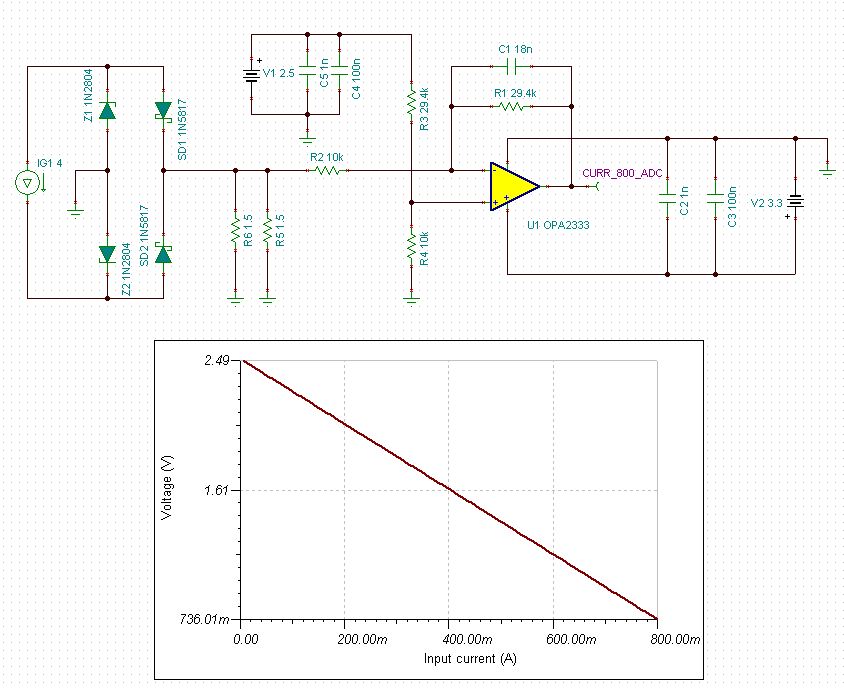
I am facing an issue with TI TINA simulation software. I have OPA2333 on current sensing and amplification circuit and I want to simulate it before implementing the same.

6406.Current_Sense.TSC

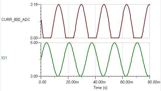
The below attached excel sheet will give the idea what is expected voltage on the OPA2333 op-amp output. But when I simulate in TINA the output oscillating on 3.3V.

6403.VT-III Current Sense Issue.xlsx

I have tried with altium designer mixed sim also but altium is giving me timestep too low error when I add op-amp to circuit. Without that it is working ok but no use.Circuit image of altium is attached below.

Please help me  to solve this issue..

  • Hello,

    I took a look at your simulation file and found that the output is responding to the input stimulus and doesn't appear to be oscillating at 3.3V, see image below. 

    Could you pleave provide a short decription of your desired input current range and desired output voltages?  The way you have the op-amp configured you'll get an inverting gain of ~ -2.94V/V from the input current that will subtract from the voltage applied to the non-inverting input which will have a non-inverting gain of 3.94V/V.  Perhaps there is an easier way to achieve what you're trying to do. 


  • The current input actually is a secondary of a current transformer with 1:1000 turns ratio that is when 1000A flows through the primary of CT we get 1A on secondary. In the attached excel sheet I have explained the voltage level in each section and my expected output voltage.

    4774.VT-III Current Sense Issue.xlsx

    In the excel the 1st three coloum represents the CT primary currrent Minimum, nominal and maximum values as the CT has 3% tolerance. Next three coloums is the CT secondary current which 1/1000 of the primary current as the CT ratio is 1:1000.

    The next three coloums  gives the input voltage range to the Op-amp amplifier circuit. The CT secondary current creates a voltage drop across this resistors (1.5R\\1.5R). i.e; 0.75R * 5mA = 3.75mV. The resistors used are of 1% tolerance.

    This voltage is applied to the op-amp circuit, as the resistor divider on the non inverting and inverting arms are the same the ouput voltage will be VREF - Vin ( RF/Rin) = 2.5 - 3.75mV( 29.4k/10k) = 2.49V at output of op-amp.

    This voltage is feed to adc input of the MSP430 MCU which converts this voltage to digital and measures the primary current. This circuit is used to measure the primary current upto 800A

      At 800A primary current the secondary current will be 800/1000 = 0.8A. This current creates 0.6V voltage drop across the resistor. This 0.6V is applied to the OPA2333  Inverting input and creates a Vout(CURR_800_ADC) = 2.5 - 0.6*2.94 = 0.74V.

    This is my understanding. Please correct me if I am wrong. Also please suggest if you have a better method. Also I am noy able to identify using which tool at TINA you have generated that output I tried with Oscilloscope but I not able to get the voltage level marking and the signal labels on the sides. Please guide me. Thanks..

  • Hello,

    Your understanding of the circuit is correct and this is an effective method to do what you're looking to accomplish. 

    There was an error in the TINA schematic you attached and the 29.4k resistor from 2.5V reference to the non-inverting input was only set to 29.4 Ohms, instead of 29.4 kOhms.  When I modified the schematic with the proper resistor value I obtained the results below that match your Excel calculations:

    To obtain these results click on "Analysis / DC Analysis / DC Transfer Function."  Then setup the source to be the input current source (IG1) and then set the range to match the range shown in your spreadsheet and then click "OK".