This thread has been locked.

If you have a related question, please click the "Ask a related question" button in the top right corner. The newly created question will be automatically linked to this question.

configuration registers for the INA226, calibration register

Other Parts Discussed in Thread: INA226

i am having trouble setting the configuration registers for my application.  I have been able to reproduce the example calculations in excel, but the part im stuck on is what to enter for my "max expected current'  im not sure how an estimated current can be used for a calculation.  i feel kinda silly posting here, because this is prob a very simple question.

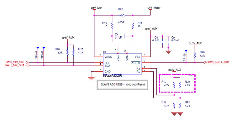
i am using a high side shunt with a value of 0.008 Ohms on a 24V circuit. 

  • Hi David,

    No question is silly question! Thanks for using our forum.

    In the max expected current you need to add the maximum current you are expecting to have in your circuit/load.

    We have a training video that might help you understand how to calibrate and configure our INA226. Please review and let us kow if you have further questions. Refer to Session 15.

    e2e.ti.com/.../467332
  • thank you for your reply, but the problem is that i do not yet know the max current. this rail is supplying power to a stepper motor driver that is still in development and the current has not yet been determined.
  • Hi David,

    Start programming the INA with an estimated current so you get familiar with the device and functions. You need to determine your final expected current for the final configuration.
  • thank you for the advice.  i now have what i believe is a good starting value, but the linearity is not what i expect.  at low current there seems to be much greater difference when compared to an in-line DMM measurement.   Is this expected? or could i have missed something my calculations?

    below is a graph comparing 4 different cal register settings over 100 -1000 mA loads.

    cal reg: 0x0260
    load IAN226 DMM % dif
    100 105 103 1.941748
    200 203 202 0.49505
    300 298 302 1.324503
    400 395 402 1.741294
    700 684 701 2.425107
    1000 975 1001 2.597403
    cal reg: 0x0265
    load IAN226 DMM % dif
    100 107 103 3.883495
    200 204 203 0.492611
    300 300 302 0.662252
    400 399 403 0.992556
    700 691 701 1.426534
    1000 982 1001 1.898102
    cal reg: 0x0270
    load IAN226 DMM % dif
    100 108 103 4.854369
    200 207 203 1.970443
    300 306 302 1.324503
    400 405 402 0.746269
    700 702 701 0.142653
    1000 998 1000 0.2
    cal reg: 0x0280
    load IAN226 DMM % dif
    100 111 103 7.76699
    200 213 203 4.926108
    300 314 302 3.97351
    400 416 402 3.482587
    700 720 701 2.710414
    1000 1026 1001 2.497502
  • Hi David,

    Can you share a excel sheet with your calculations so I can review it step by step for you?
  • I am not calculating current, i have set the calibration register so the chip is calculating the current.

    i found the problem with the nonliterary late last night.  i was not taking i to account a small parallel load on my circuit that was not part of my measurement loop.  so as i made measurements at lower and lower loads, that parallel load was a greater percentage of the applied external load.

    One additional question / comment.  In the data sheet, the calculation for the calibration resistor on of the variables is 'max expected current'  this confuses me and caused me a lot of trouble.  it seems to imply that if i only expect 10A in then i can put that in to my equation with the Rs value, come up with a current_LSB and in turn a calibration value.   But when i tested this, it just did not work.  i was not getting any where near the correct chip calculated value.   when this failed i tried arriving at a calibration empirically.  after a few tests i was able to get a value that would allow the chip to calculate the proper value (the value i was measuring by loading the output of the chip with a programmable load.   using that value i went back to my spreadsheet to revers calculate my 'max expected current'.  this resulted in a value of 34A - not at all what i expect to see in this circuit.  it seems to me that the only way to actually change the dynamic range of the circuit is to change the Rshunt resistor value.  because all of the measurements are based on the voltage across Rshunt and the voltage on Vbus.  in other words, just be cause i dont 'expect more than 6-7 amp load, it will not change the LSB that is the result of an 8mOhm Rshunt.

    please explain if i am mistaken. 

  • Hi David,

    You are correct. The dynamic range will be based on the shunt resistor. The current value will be based on that voltage and the calibration register value. I am a little bit confused with the current issue you are having. Can you please use the calculator I am attaching for your setup? I already modified it with your values.INA226_Cal_workbook.xlsx