This thread has been locked.

If you have a related question, please click the "Ask a related question" button in the top right corner. The newly created question will be automatically linked to this question.

TINA TI simulation ,strange result of opamp capacitive load of LM7321, OPA830 and LMV321

Other Parts Discussed in Thread: OPA830, LMV321, LM7321, LMV324

Dear Spelialists,

(1)My customer is simulating opamp capacitive load by TINA TI, but he can't get good results.

Please see attached file. (question about simulation result)

Could you please advise what is the problem.

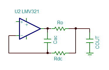
(2)And then I made a circuit by using TIDU032C as a reference, it may be strange.

please comfirm attached file(phase margin of 10nF load between LMV321, OPA830 and LM7321)

Because the LM7321 is for unlimited capacitive load, but phase margin is quite small at only 10nF.

Could you please advise.

I appreciate your great help.

Best regards,

Shinichi

1682.question about simulation result.docx

6472.phase margin of 10nF load between LMV321, OPA830 and LM7321.docx

  • Shinichi-san,

    LMV321 simulation is likely a little optimistic. I would expect the phase margin to be lower.
  • Shinichi-san,

    For the LM7321, there is a graph of Cload vs. Phase Margin on page 17 (fig 45). With a 1000pF load, the phase margin is at 30°.

    Note - Unlimited cap drive does not mean it will perfectly drive a capacitve load with perfect 60° PM and square edges. It means it will not have sustained oscillations.

    The small signal step response graph (fig 49) shows some heavy ringing at 1000pF. Also see Figure 61 in the apps section.

    The LM7321 model is an older one, and models output impedance as a fixed value. So it will not accurately mimic the actual device response. Same for the LMV324 model (assuming this is the old National model - which can be seen if you right click on the symbol and click "enter Macro".

    The best test is the actual circuit, as load conditions (resisitve and capacitive) affect the stability.

    Regards,
  • Dear Paul and Ron

    Thank you for your reply

    I under stand the simulation model of LMV324 and LM7321 are not accurate.
    They aren't appropriate for capacitive load simulation, right?

    By the way, how do you think question about simulation result.docx of Fig. 1,Fig. 4 and Fig. 7
    Is there any problem for capacitive load simulation?
    If a simulation model is ok, it can be get the correct result?

    I appreciate your great help.

    Best regards,
    Shinichi
  • Shinichi-san

    I suggest using the Riso resistor to improve phase margin. Getting 60 degree in simulation is a good target.

    The topology can be changed to support driving high capacitance.

  • Dear Ron 

    Thank you for your reply.

    I agree.

    At the actual circuit, it should be added an isolation resistor. 

    I think the customer use this solution after all.

    The simulation is an advance confirmation.  

    In the meantime, it is not mentioned OPA830.

    About OPA830, Is there any problem of simulation model, or not?

    Also, could you please advise the result of OPA830 simulation of attached file(again)

    The circuit is used TIDU032C of Figure 4. as a reference.  

    I'd like to know this result is OK or not.

    I appreciate your great help.

    Best regards,

    Shinichi 

    5460.6170.phase margin of 10nF load between LMV321, OPA830 and LM7321.docx.