This thread has been locked.

If you have a related question, please click the "Ask a related question" button in the top right corner. The newly created question will be automatically linked to this question.

OPA211: OPA211 Output Current

Part Number: OPA211
Other Parts Discussed in Thread: OPA172, OPA2172

Hi All,

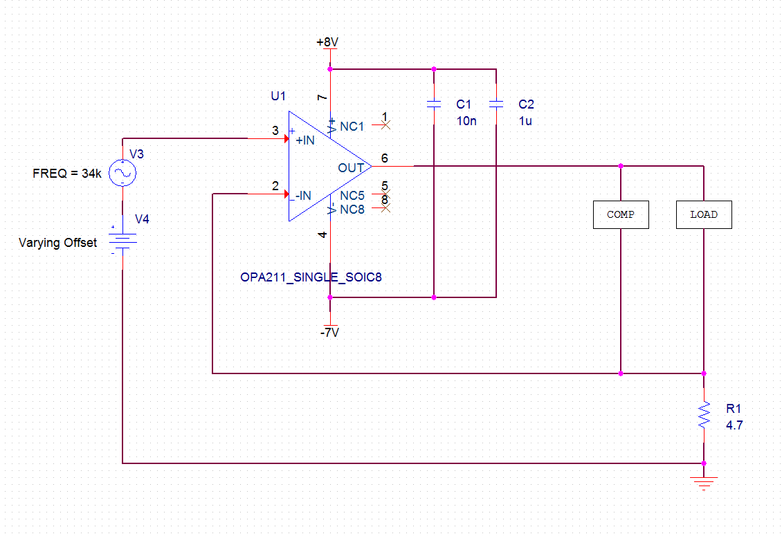
I am using an OPA211 for a robotics application in a non-inverting VCCS configuration and had some questions about the output current characteristics.  The load is primarily inductive and resistive and also highly nonlinear. The load impedance is low enough 3.5V headroom is maintained on the positive side and 2.5V on the negative side.  COMP is some frequency compensation for stability and transient response.

The datasheet indicates typical values @25C for short circuit sinking and sourcing currents (-45mA and +30mA) as well as a graph (figure 23) of how both of these values vary with temperature.  Since my application will have symmetrical maximum current, I am concerned only with the lower of the two limits (in this case sourcing).

It also provides a figure relating the maximum output current to the available voltage headroom shown below:

Over let's say 0-150C temperature range the two graphs seem to suggest different sourcing capabilities:

Figure 23 would suggest ~26.5mA based on the performance right at 150C

Figure 37 would suggest ~32mA based on the 3.5V headroom I maintain, also at 150C

My first question is: what is the reason for this apparent disagreement between the two ratings?  Is there a difference in input overdrive in the test conditions that I am missing? 

----------------------------------------------------------------------------------------------------------------------

My second question is essentially, _roughly_ how much could I expect [whichever of the above 2 potential current ratings I should abide by] to vary from chip to chip?  Since minimum and maximum values are not specified in the datasheet I was going to assume that it may vary extremely.  I am not looking for any guarantees and no one's safety is riding on this circuit, just inconvenience for me.  I am simply looking for a reasonable rule of thumb or ballpark guess from the actual makers of the device to help determine a sensible amount of margin to give myself in this design.

Help is much appreciated, thank you.

  • Dominic,

    Please see my answers below:

    Over let's say 0-150C temperature range the two graphs seem to suggest different sourcing capabilities:

    Figure 23 would suggest ~26.5mA based on the performance right at 150C

    Figure 37 would suggest ~32mA based on the 3.5V headroom I maintain, also at 150C

    My first question is: what is the reason for this apparent disagreement between the two ratings?  Is there a difference in input overdrive in the test conditions that I am missing? 

    There is no disagreement between Fig 23 and Fig 37 – the short circuit current at 150 deg C gets engaged at the Vout knee (~26.5mA) and not some arbitrary headroom of 3.5V from the rail – see the red circles below.


    My second question is essentially, roughly how much could I expect [whichever of the above 2 potential current ratings I should abide by] to vary from chip to chip?   Since minimum and maximum values are not specified in the datasheet I was going to assume that it may vary extremely.  I am not looking for any guarantees and no one's safety is riding on this circuit, just inconvenience for me.  I am simply looking for a reasonable rule of thumb or ballpark guess from the actual makers of the device to help determine a sensible amount of margin to give myself in this design.

    The variation in the short-circuit current for the parts coming from the same wafer lot is very small - perhaps +/-5% - but Isc may vary as much as +/-25% from its typical values shown in the datasheet for lots coming from wafer lots fabricated several months apart - this Isc variation is mostly due to variation in the wafer process sheet resistance.

    Having said that, a short-circuit current protection is there to prevent damage to IC caused by accidental shorting of the output and NOT for the customer to rely on in their system design.  Therefore, the only guaranteed OPA211 output current is specified to be +/-15mA – see datasheet table below – and it is the only Iout specification tested in production.


  • Thank you very much for your answer. Everything you said makes sense, I definitely did not understand that the short-circuit current rating is defined by the knee in the Vout curve.
  • Hi Marek,

    Thanks again for your insight. If I could attach one more related question:

    For a drop-in replacement amplifier to the OPA2211 in the DRG package I will be limited to the OPA172 based on AC specifications. However, the 172's datasheet does not include an output current limit in the testing conditions for the voltage output range like the OPA211's does, which you pointed out to be the only guaranteed and tested rating.


    Would the next best thing be to consult the output current vs output voltage graph the 172's datasheet provides, find the worst case current output for the headroom I have in my application, give myself 25% derating for wafer process sheet resistance, and then some additional safety factor depending on how aggressive we'd like to be?

    Thanks,

    DR
  • Dominic,

    The only OPA2172 output current limit tested in production is part of the AOL test - see datasheet table below:

    Thus with the maximum supply voltage of +/-18V and RL=2k connected to mid-supply (ground), the output, Vout, swings within 0.5V of either rail; therefore, under such conditions Iout=(18V-0.5V)/2k=8.75mA. 

    Beyond the above tested Iout level, you must use the Output Voltage Swing vs Output Current typical graphs shown below. Just rememeber that these graphs show the output swing at the point were the output transistors get trioded - a non-linear operation where Ron of the output transistor determines the Vout swing.  For that reason, in order to assure that the smal-signal is able to propagates thru the op amp, Vout must be kept further away from the rail than the typical curves shown below indicate - the safety factor you suggest sounds reasonable.