This thread has been locked.

If you have a related question, please click the "Ask a related question" button in the top right corner. The newly created question will be automatically linked to this question.

XTR111-2EVM: 1) 4mA shift adjust w/ps other than 24V?, 2) how squelch noise?

Part Number: XTR111-2EVM
Other Parts Discussed in Thread: XTR111

Even though the eval board says it can take an 8-40V power supply the pdf says to set it up with a 24V ps(?)...

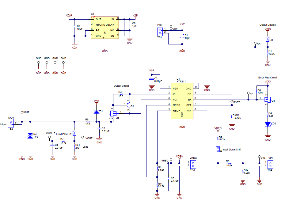
Question1: If I use a ps other than 24V do I need to adjust R6 to still get 4mA out w/0V Vin? (and what is the formula to do so?)

Question2: I see how to set Rset so that my max Vin = 20mA Iout but how do I setup the eval board such that my min Vin = 4mA Iout?
(ie I may have noise...) Would I change R8 to squelch my noise and then readjust Rset?

I have read the eval board tech pdf but admittedly only to pg12 of the XTR111 tech pdf which explains things in greater detail...

Thank you!

Best,

P

  • Hello,

    The EVM will operate over the full supply voltage range.  The LDO and other circuitry on the EVM supports supply voltages above the XTR111 supply voltage.

    1.)  The VREG output is based on the XTR111 internal regulator circuitry and will maintain a constant VREG output voltage.  Therefore, R6 doesn't need to change with supply voltage.

    2.)  By installing J3 the output should shift to 4mA when the input is 0V.

  • Thank you Collin!

    2) Yes but say I have ~200mV noise and I want a 200mV input to equal a minimum Iout of 4mA (ie instead of 0V = 4mA, 200mV = 4mA)?
  • Increase the value of the offsetting resistor to 49.9k and it will work as you'd like.  See results and simulation files below.  Note that this is an unofficial simulation model that's useful to understand the basic functionality of the XTR111 but does not model the parametric behavior.  Refer to the datasheet for information regarding performance specifications.

    XTR111_200mV_4-20mA.TSC

  • Thanks Collin!, 

    It appears from your schematic above you are referring to R10 but looking at the evaluation module schematic I'm not seeing an equivalent resistor?  Can you specify resistor number on the evaluation board that enables this adjustment? (and a formula if available to calculate proper R value based on noise V?)  Thank you!!!

    Best,

    Pete

  • Hi Peter,

    It's R6 on the EVM, see image at the bottom of this message.  The offsetting resistor works to form a basic voltage divider with the 10k input resistance such that when the input voltage is 0V (or 200mV) the VIN pin on the XTR111 sees the proper voltage to output the desired low-level current.  With RSET = 2.49k, we need roughly 1V on the input to achieve a 4mA output current (Vin = Io*RSET/10).  Therefore the divider was set up based on the equation shown next to the circuit below.

    Voltage Offset.TSC

  • Hi Collin,
    I've got my system together (changed Rset to 5.49k) but:

    1) with J3 shorted (J1/J2 open), 0 Vin = 2mA Iout instead of 4mA...and

    2) max Iout occurs with a Vin of 11.1...above 11.1V Iout goes down?!?

    Thoughts? Thank you!!
    Best,
    Pete
  • Hi Peter,

    You'll need to change some of the other components in the system to make up for the change in RSET resistance. What are your desired input voltage / output current ranges?
    For example:
    Vin = 0.2V - 5V
    Iout = 4mA - 20mA
  • Vin = 0-11V

    Iout = 4-20mA

  • Do you no longer have the requirement you originally asked about where Vin = 200mV equals 4mA?
  • Hi Collin,

    It took me until today to get an answer to this.

    Based on some initial tests our minimum Vin is currently right around 1 Volt which is currently getting me ~3.2mA out of the TI eval board.

    1) What would I need to change so that 1V in = 4mA out?

    2) What would I need to change so that max output (10.6Vin) is 20mA instead of the current 17.2mA?

    Thank you!!

    Best Regards,

    Pete

  • Hi Collin,
    Based on initial tests our minimum Vin is currently right around 1 Volt which is currently getting me ~3.2mA out of the TI eval board.

    1) What would I need to change so that 1V in = 4mA out?

    2) What would I need to change so that 10.6Vin = 20mA out instead of the current 17.2mA?

    Thank you!!
    Best Regards,
    Pete
  • You'll need to change a few things.

    First change the VREG output to 10.6V by changing the resistor divider values to 5k and 12.7k

    With VREG at 10.6 you can size the offsetting resistor for the 1V offset at 75k with a 10k input resistor.

    The Span will be set with the RSET resistor.  A value of 5.3k is required for a 20mA output with a 10.6V input.

  • Here is an example circuit and the results.

    XTR111_1V-10p6V_4-20mA.TSC