- Ask a related questionWhat is a related question?A related question is a question created from another question. When the related question is created, it will be automatically linked to the original question.
Hello support team,
I'd like to know the measurement circuit for the quiescent current of OPA376.
According to the datasheet of OPA112, the following sentences are stated as conditions.
"At TA = 25°C, RL = 10 kΩ connected to VS / 2, VCM = VS / 2, and VOUT = VS / 2, unless otherwise noted."
From this, I guess the measurement circuit for quiescent current may be as follows.
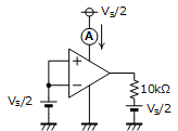
Is my understanding correct?
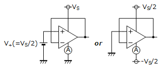
And when under the following condition, I guess the circuit will be as follows.
"TA = 25°C, IO = 0, VS = 5.5 V, VCM < (V+ ) – 1.3 V"

In this circuit, I guess the circuit current at when the output is on the plus side rail voltage is measured.
Is my understanding correct?
Please correct them if there is a mistake.
Best regards,
M. Tachibana