This thread has been locked.
If you have a related question, please click the "Ask a related question" button in the top right corner. The newly created question will be automatically linked to this question.
HI, I am using opa2197.
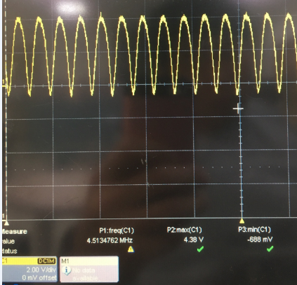
When the following circuit is operated, the output switches.
AO_O wave.
Adding a bypass cap 10nF to ao_0 will not cause this switching.
The problem does not occur when used with opa2188.
What's the problem?
Leonardo,
I presume your circuit includes the current path to ground from the drain of T2 (AO_0). If so, it should work just fine and the problem you describe is most likely related to the lack of compensation caps across the gain stages (from gate to drain) - see below. Please try to add caps as shown on the schematic below and see if that fixes the circuit stability issue - 100pF shown on the schematic below is just a placeholder and you may have to try diifferent values to optimize the solution.
Leonardo,
The application circuit you implemented has inherent parasitics (junction capacitances), which create higher-order system. Since each pole results in 90 degrees phase shift, two pole (180 degrees shift) or higher order system will be inherently unstable. For that reason, you must compensate it in order to create a single dominant pole at the lower frequency while pushing parasitic poles above the bandwidth of the system. This is similar technique used in compensating any op amp - so called Miller compensation.