Because of the Thanksgiving holiday in the U.S., TI E2E™ design support forum responses may be delayed from November 25 through December 2. Thank you for your patience.

This thread has been locked.

If you have a related question, please click the "Ask a related question" button in the top right corner. The newly created question will be automatically linked to this question.

LF356: lf356 gain problem

Part Number: LF356

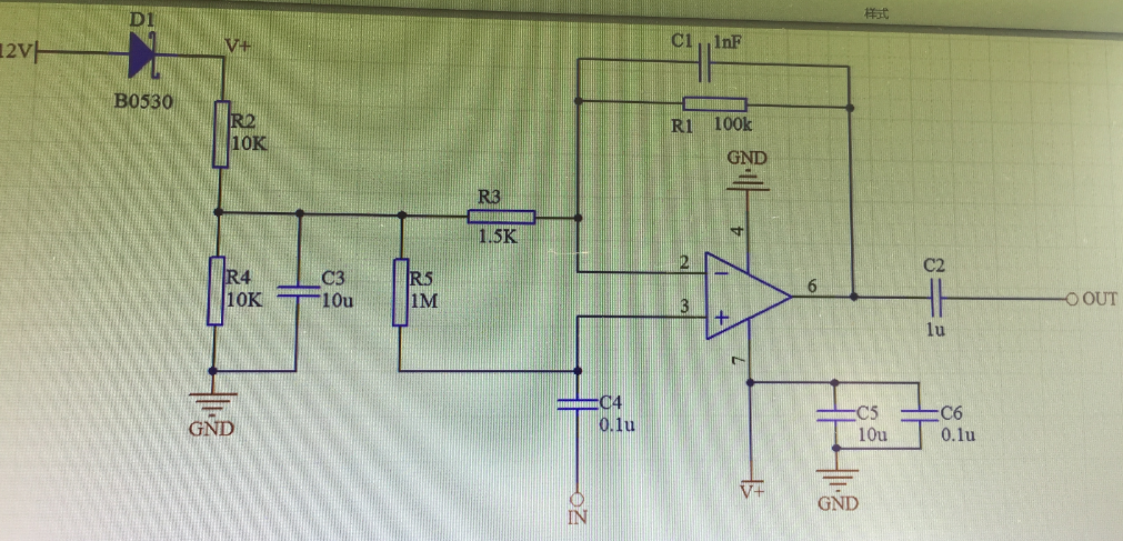
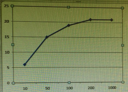
Hi, i am use lf356m now, the sch is above, but the gain is smaller when the input signal frequecy is low, the gain response is like above, the x axis is frequency, the y axis is gain, please help find out the reason, i hope that gain is same no matter the input frequency. thank you!

  • Part Number: LF356

    Hi, i am using lf356m to design an amplifier, but i find that when the frequency is low, such as 10, 20 or 50Hz,the gain is much smaller than i hoped, the sch and gain response is like below, the x axial is frequency , the y axial is gain number. please  help to find out the response, thank you.i hope that the gain is same no matter the frequency low or high.

  • User,

    Let's Start with the simple poles and zeros
    Input zero is 1/(2pi*C4*R5) = 1.6 Hz, so it will be flat above 16 Hz
    Gain pole is 1/(2pi*C1*R1) = 1.6 kHz, so it will be flat below 160Hz

    Because both R5 and R3 tap the same 1/2 VCC supply then interaction across frequency will be complicated.
    Notice that R3 < R2||R4 so the voltage divider resistors are a significant part of the inverting ground resistance.

    Do you want the same gain for the DC component of your input signal? If not what is the desired low frequency cutoff?
    What is the maximum input frequency? What is the maximum output amplitude (so I know how much slew rate is needed)
  • Hi Ronald,

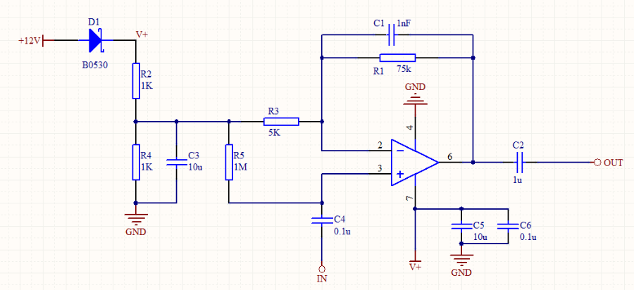
    Thanks a lot for your help, i have changed the circuit as below, and gain works good now,

    I don't want to amplify the DC component of the input signal, i want the low frequency cutoff is 5Hz, the high frequency cutoff is 2000Hz,

    what i need to do to realize the above two cutoff?

    the maximu output amplitude is less 1V.

    Thanks again.

    Michael Ding.

  • What was the lower cutoff with your circuit? It looks like 1.6Hz to me. 

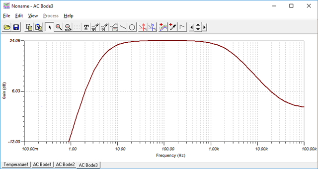
    Here is a 7Hz to 2kHz modified version. Using free TI-tina

    LF356.TSC