This thread has been locked.

If you have a related question, please click the "Ask a related question" button in the top right corner. The newly created question will be automatically linked to this question.

INA168: INA168

Part Number: INA168
Other Parts Discussed in Thread: INA240, INA138

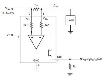
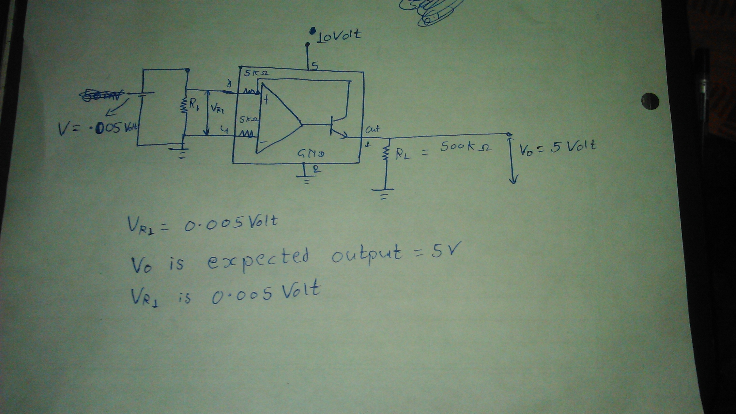
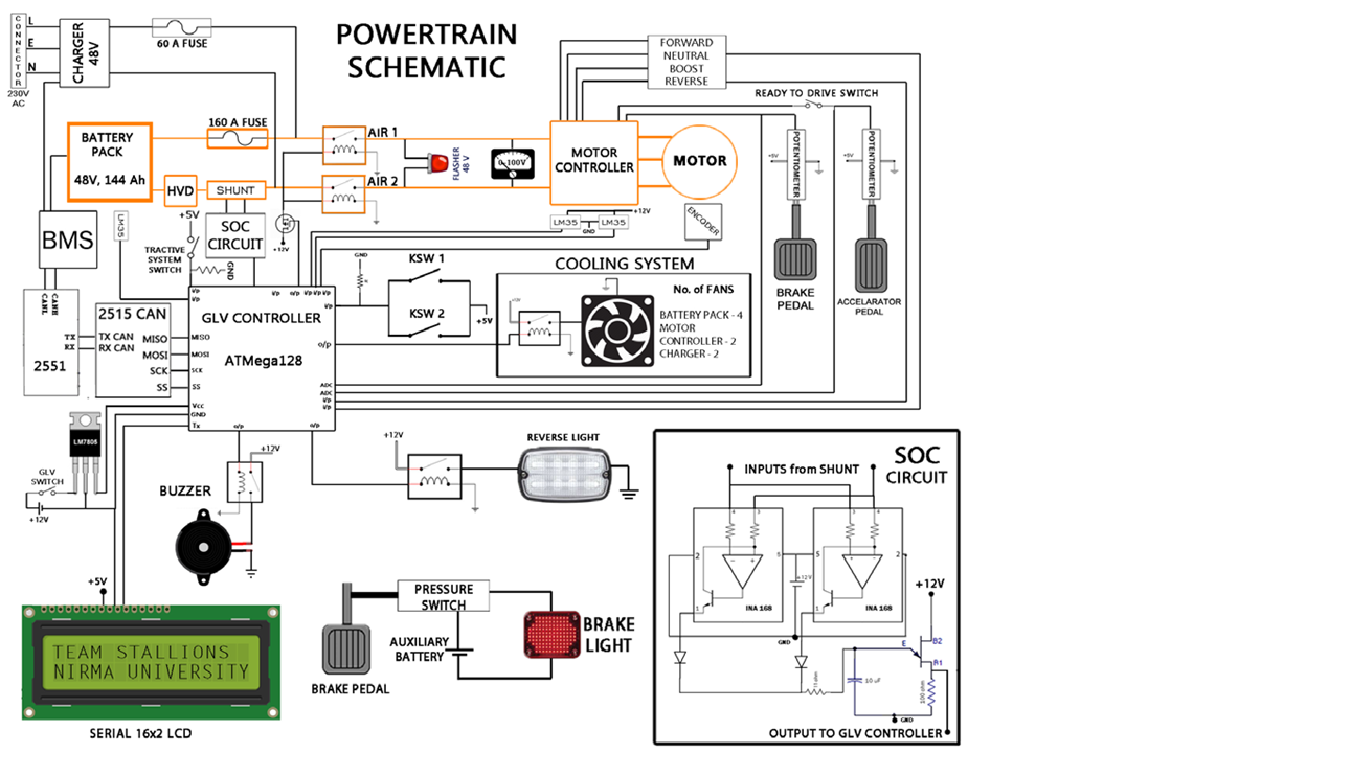
I have a 48v , 144AH DC battery and on negative terminal there is a current shunt and I want to measure current through this shunt with the help of INA168 . I had take two wires from two terminals of current shunt and there  two wire are acting as inputs of INA168 and  at output side there is a load resistor across which  I am measuring ampified voltage and gain of this circuit  depends upon output resistor but   I am getting only unit gain this is the problem that i am not getting gain more than 1. my circuit is attached here.


  • Hello,

    May you please provide a schematic and more circuit information such as what the current load, shunt resistor, and expected outputs are?

    Sincerely,
    Peter Iliya
  •  5volt is expected output voltage but i am getting 0.005Voltage at output side . I had changed input voltage but still getting voltage gain of 1.

  • Why do you expect your output to be 5V?

    According to your photo, Vout should equal 500mV according to the equation:
    Vout = Is*R1*200uA/V * RL
    Vout = Vr1 * 200uA/V * RL = 0.005V * 200uA/V * 500kOhm = 500mV.

    Is this photo representing that you are doing a low-side application in which your common-mode voltage (Vcm) = 0V? Basically, is the voltage seen a pin 3 equal to approximately Vr1 (~5mV)? If this is the case, then you are operating the device outside of its common-mode voltage range of 2.7V < Vcm < 60mV and thus your Vout is useless. Consider making this a high-side application or choosing a current shunt monitor designed for low-side applications (its Vcm range can go to 0V or below). INA240 would be an example.

    Also, conisder raising your R1 value and thus raise your Vr1 from 5mV to something in between 100mV to 500mV for the most accurate measurements. The input offset (Vos) of the INA168 can be up to +-1mV, which would generate immediately 20% error, not even including effects on accuracy from CMRR, PSRR, gain drift, etc.

    Peter Iliya
    Current Sense Applications
  • #include<LiquidCrystal.h>
    #include<Wire.h>
    #include<EEPROM.h>
    
     LiquidCrystal lcd(12,11,5,4,3,2);
      int count = 0; // This variable is counting impulses
      int  p0 = 1;
      int a=0;
       
      float USOC=100;
      int addr = 0;
      
       float SOC = 100; // SOC 100 means battery charge level 100 percent
      void setup()
      {
          lcd.begin(16,2);
          pinMode(p0,INPUT); // Input from UJT output for impulse output.
      }
    
    void loop() 
      {
          lcd.setCursor(0,1);
        lcd.clear();
        int input = digitalRead(p0);
         while (input == 1)
         {
           if (input == 0)
           {   
          
          if (a==0)
          {
          
          count += 1; // Count variable is counting impulses
         float countp = count*100/5781.23;/*Countp variable indicates how much battery get discharge where 5781.23 is total number of impulse we will get when our battery will fully discharged which is calculated by battery Charge when battery is fully charged .*/
         SOC = SOC - countp; // this is the rest of battery charge
         a=1;
         
          }
           }
         }
          if(a==1)
          {
            a=0;
          }  
         
        lcd.print("SOC: "); 
        lcd.print(SOC);
        lcd.setCursor(0,2);
        lcd.print(count);
        delay(100);
     
      }
      

      Tarun Ti.pptx

    My Vr1 voltage is variable ranging from 3mv to 40mv  and I want output in rang of 3voltage  to 10voltage this voltage output should be linear  with the help of INA168.

    - I required above results because We are Engineering students and we are making a Electrical ATV (ALL -TERRAIN-VEHICLE) and we have a battery of 48v, 144Ah and one Induction motor for wheel . Now we had made our ATV.

    - But problem is When our vehicle runs on a  track  current through DC battery is upto 153A(From motor power we had calculated it).

    - We want to know that how much our battery get discharge while running . So I take taping from current shunt this is the input for INA168 and output of INA168 is we expect in range of 3v to 10v (linear) so that my SOC (state of charge )Circuit will work .

    - Attachment here is this power train diagram of our ATV and in orange colour outline is the main area and  my SOC circuit is connected to current shunt  which consist INA168 , UJT, Capacitor  .

    Use of each SOC component -

    INA168 - To amplify voltage across shunt as our our requirement as data given . We had measured voltage across shunt ranging from 3mv to

                      50mv  and we want voltage output ranging from 3v to 10v (linear ).

    UJT(Unijunction Transistor ) - this is acting as a ujt-relaxation-oscillator for coulomb counting method for current measurement .

    out put of UJT is impulses due to capacitor get discharge when capacitor get charged upto a contant voltage and UJT get triggered and we get impulse at UJT outputside . From Arduino uno we calculate impulse and calculate actual current flowing through the circuit .

    - Capacitor charged upto a constant voltage if current flowing through the main power traing changes then distance between impulse vary

     because as current increases  capacitor charges faster and get discharge faster so we get impulse faster and we know charge of capacitor    

    Q = C * V.  Q is constant because  C is constant and V is constant ,V is constant because UJT triggering voltage is constant .

    - I had  attached my simulation file which is done on Proteus simulation software .

    - I had also attached my arduino program file . In this arduino  I had write programme  .

    - We don't know about shunt resistance but voltage across it we had measured as above through multimeter.

    - Sir now all things I had given to you but this all depend upon INA168 which is not amplifing according my requirement . Please help .

    Sincerely,

    Tarun Singhal

  •  This is the power train of our ATV.

  • Hello Tarun,

    1. Why do the simulation file circuit and the SOC circuit from the last image not match? There is no shunt resistor seen in the simulation file and I'm not sure exactly how they are supposed to correlate.

    2. Are you sure the INA138 is actually ouputting enough current to turn on the 1N4148 diodes? According to the Diodes Inc datasheet, you need at least 400uA to foward bias the diode to 0.5mV. If your max Vshunt (or Vr1 or Vsense) voltage is 50mV, then your max Iout of the INA138 is = 200uA/V * 50mV = 10uA. Keep in mind that the INA138 or INA168 does not output a voltage. It drives a current which is usually converted into a voltage using a load resistor.

    3. How are you discharing the load capacitor C2?

    Peter Iliya
    Current Sense Applications
  • Sir , I need your one more help that I have given you all the details of my ATV power train and I want to measure how much our battery get discharged when our ATV is running and during running condition current through battery is varying if I use INA 240 across Shunt resistor in Power train and for counting pulses  i am using my UJT Relaxation OSCILLATION circuit .

    Sir , I think  you have got all the idea what i am trying to do So according to you what should I do .

  • Hello Sir,

    1. In simulation diagram 0.003 ohm resistor(we had assumed shunt resistor 0.003ohm) is my current shunt .

    2. C2 capacitor is discharging through UJT relaxation circuit, which will impulse and I will count impulses through arduino.

    Sir if I use INA240 then what should be circuit diagram according to you.
  • Hello again,


    Just to confirm, using the INA168 will not work in the schematics you have provided because the INA168 is a high-side current measuring device and you are using it in a low-side configuration.


    The INA240 can work in this situation. I would recommend the following low-side circuit for the INA240A3 (gain 100V/V) referenced to ground. Here I am removing the UJT relaxation oscillator since it would not be needed. If you need bidirectional current measurements, then you would have to reference the INA240 to 2.5V and reduce the gain to 50V/V.


    Here is another possible circuit using one high-side INA138. I increased the Rshunt to 9 mOhms to boost the Vshunt to 9mV at a minimum to provide best accuracy. If want Vout to go to 10V during max current, then you will need to power the part with at least 11V (see equations 1 and 2 in the INA138 datasheet. RL = 125 kOhms


    Finally, if you must have bidirectional current, then you could use the application circuit example from the INA138 datasheet seen below. This would have to be a high-side current application.


    Hope this helps,

    Peter Iliya

    Current Sensing Applications