This thread has been locked.

If you have a related question, please click the "Ask a related question" button in the top right corner. The newly created question will be automatically linked to this question.

Appication problem for AMP

Other Parts Discussed in Thread: TINA-TI, OPA1678

Hi team,


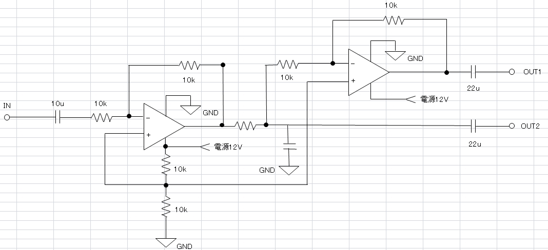
My customer want to use two opa to convert the audio single ended signal to differential signal, as show in below draft sch, for long distance transmission.

And they want to know how to calculate or test the output resistance of the differential signal? Could you please share some document regarding to this case?

Thanks a lot!


  • Hi Fery,

    this is a strange circuit. Where do you have it from?

    Kai
  • Hi Kai,

    Customer design this circuit by their own. Is that workable to convert single-ended signal to differential signal?
  • Hi Fery,

    outputs OUT1 and OUT2 are not really symmetric because of the resistor and cap without values. Is this a drawing mistake?

    Kai
  • Hi Fery,

    As long as the customer is using an op amp with a modern SPICE model which simulates open loop output impedance and open-loop gain of the amplifier, the output impedance of this circuit can be easily simulated. For more information on how to do this, see this blog post by my colleague, Tim Green. 

    I went ahead and built the circuit above in TINA-TI (file available here) using OPA1678 as the op amp. Since no values were provided for the R/C filter, I omitted it from my initial simulation. For this circuit, the 22µF output capacitors dominate the output impedance across the audio band. The differential output impedance in this case drops from ~730Ω at 20Hz to ~0.5Ω at 20kHz. Adding a 10Ω resistor and 16nF capacitor (100kHz LPF) for the R/C network, results were very similar across the low frequencies, but levelled off around 20 ohms as the R/C network resistance began to dominate over the output capacitors. 

    A couple of notes: 

    1. In the event of a short, or a long cable length on Out1/Out2, the op amp outputs will likely become unstable due to the capacitive load. It would be a good idea to add some resistance (say 50Ω) after each amplifier (this is already in place on the first amplifier, as part of the R/C)

    2. measuring this in the lab should be relatively straightforward: use a function generator connected to the outputs through a known resistance, then measure voltage at Out1/Out2 and voltage across the resistor. Voltage across the resistor can be used to calculate current, which can then be used along with the measured output voltage to calculate output resistance of the circuit. 

  • Hi Fery

    We haven't heard back from you so we assume this resolved your issue. If not, post a reply below, or create another thread if this one has timed-out.

    Thanks
    Dennis