- Ask a related questionWhat is a related question?A related question is a question created from another question. When the related question is created, it will be automatically linked to the original question.
Hello,
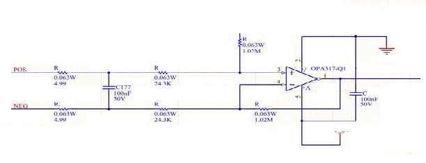
A previous engineer designed this OPA317 circuit and we could use help with an analysis.
We’d like to lower the fC on the differential filter, but the calculated capacitance becomes fairly large. Do you know why they would have split the resistance on the input to the diff amp? 4.99Ω seems to be an awful specific value but it is not covered in his design document. Why not place the filter cap across the inputs to the amplifier itself and save the two extra resistors? Does this cause a stability issue with the amplifier at high f?
I can share a more detailed schematic by email.
Thanks very much for your help. Keith