Other Parts Discussed in Thread: ADS41B49,
Hi,
I am currently testing a THS4541 to drive the input of the ADS41B49 ADC.
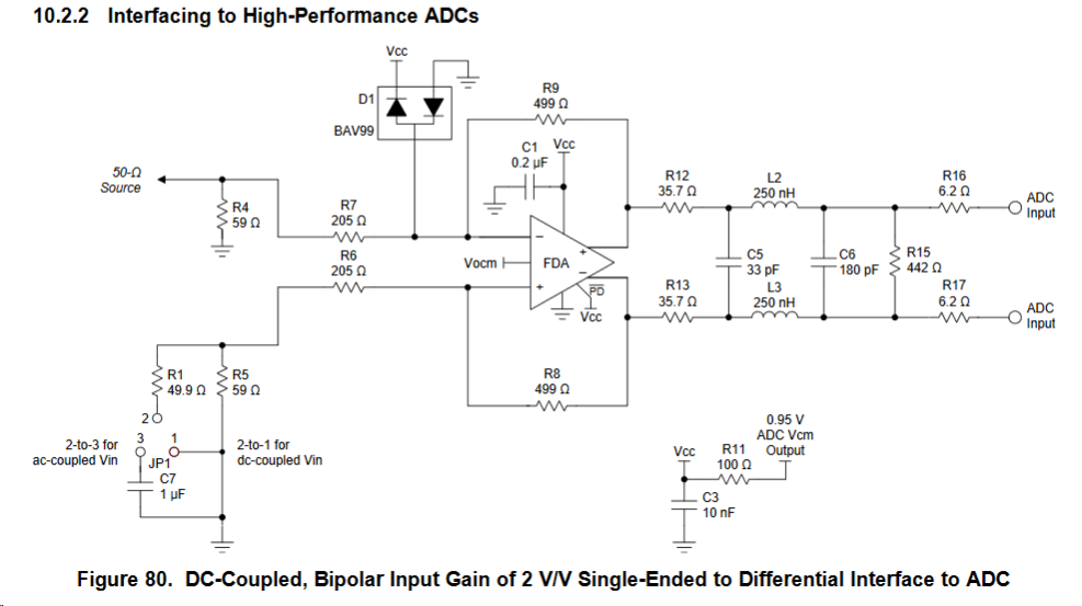
The input is DC coupled and I am using the recommended circuit specified in the THS4541 datasheet (Figure 80, page 47)
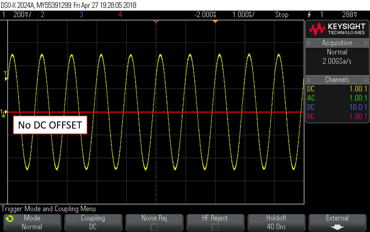
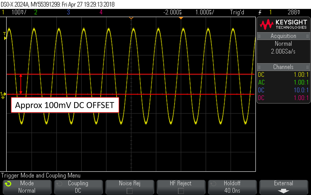
The issue I am having is that when I connect anything at the input, the THS4541 "pulls up" the signal a couple of hundreds mV. For instance when I apply a Sinewave of +-500mV reference to zero, the reference changes to approx 150mV. IT gets back to zero when I disconnect it. Is this behavior expected? Any pointer of what could causing it? The Protection diode perhaps?
The only difference I see between the circuit in the datasheet and my implementation is that the ADS41B49 has a1.7V Vocm instead of a 0.95V. Could that be the cause?
Thanks in advance for your help