This thread has been locked.
If you have a related question, please click the "Ask a related question" button in the top right corner. The newly created question will be automatically linked to this question.
Dear TI precision lab,
I have two questions regarding the TI precision lab FDA-part 2 and hopefully, someone can help here.
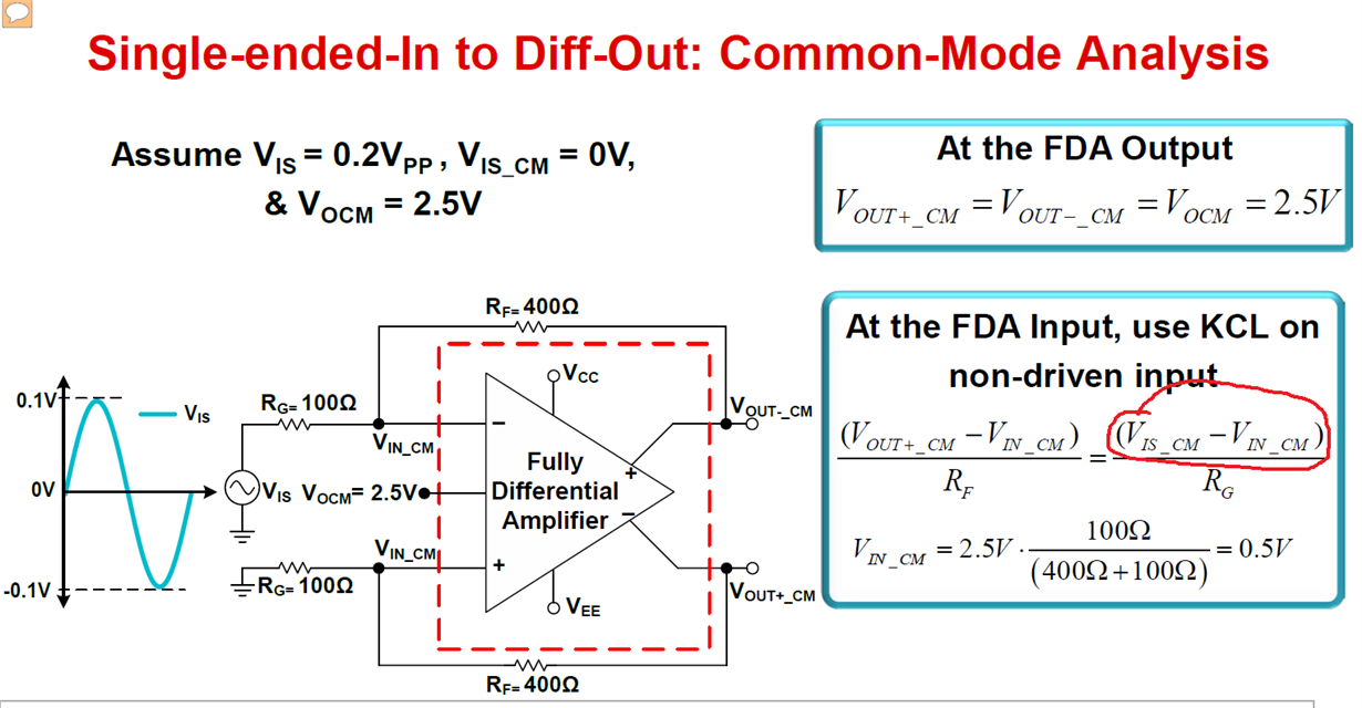
1. On Page 5 of the PPT of TI precision lab FDA-part 2, the equation that calculate the Vin_cm at non-driven input is (Vout+_CM - Vin_cm) / Rf = (Vis_cm - Vin_cm) / Rg. This indicates that Vis_cm is larger than Vin_cm. Since Vis_cm is zero, Vin_cm is negative. But actually, Vin_cm =0.5V. Please correct me.
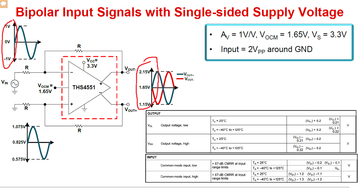
2. On Page 8 of the PPT of TI precision lab FDA-part 2, why the output is 1Vpp when the input is 2Vpp and Gain is 1V/V?
Thanks,
Hi B.Fan,
Let me shed some light here.
1. There is an error in this formula. It should be this:
(Vout+_CM - Vin_cm) / Rf = (Vin_cm - Vis_cm) / Rg
then plug in the known values and you get: (2.5-Vin_cm)/400 = (Vin_cm - 0)/100
Which simplifies to : 2.5-Vin_cm = 4*Vin_cm, then 2.5 = 5*Vin_cm and you get Vin_cm = .5V
We do plan on correcting that. Thank you for catching this.
2. I can see where your confusion is coming from. The output graph is showing the output voltage of each Vout+ and Vout-, not the differential output voltage, (difference of voltage between the output pins).
Does that make sense?
Regards,
Robert
Hi B.Fan,
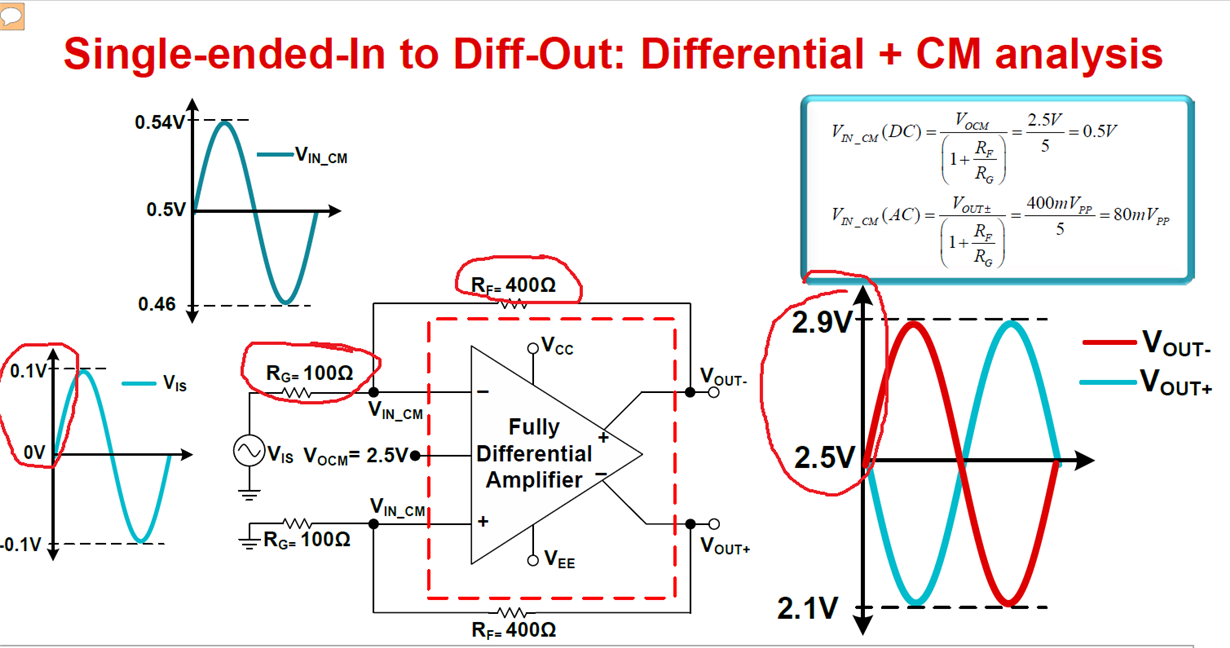
Ah yes you found the other mistake we made in the presentation. Those voltage swings should be from 2.7V to 2.3V not 2.9V to 2.1V.
If the single-ended input is 0.2Vpp, then the differential output should be 0.8Vpp if the gain is 4V/V.
We are fixing this mistake as well.
Regards,
Robert Clifton
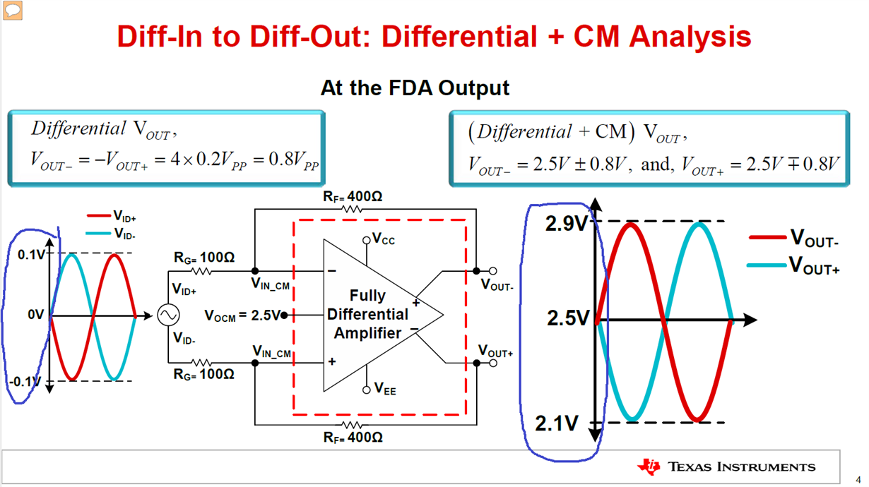
If you look at diff-in to diff-out on Page 4, both input terminals have signal 0.2Vpp but opposite direction, the output is 0.8Vpp for both of them with Gain of 4V/V.
But for single-in to diff-out, on Page 7, one end has signal 0.2Vpp and output is 0.4Vpp for both of them with Gain of 4V/V. This is the half of the values for diff-in to diff-out. This makes sense since the non-inverting terminal is grounded. But what is the mechanism behind it to move the 0.4Vpp from its original 0.8Vpp to the other end of the output?
Thanks,
BF
Hi B.Fan,
Let's go back to the differential analysis formulas:
For differential in to differential out the formula (found on page 3):
Let's plug in the values looking for Vout+ and Vout-:
ΔVout/(-0.2Vpp - 0.2Vpp) = -400/100
That simplifies to ΔVout = 1.6Vpp, and since we know that Vout- = -Vout+ we can divide ΔVout by 2 and get
Vout- = -Vout+ = 0.8Vpp
For single-ended in to differential out the formula (found on page 6):
Let's plug in the values looking for Vout+ and Vout-:
ΔVout/(0.2Vpp) = -400/100
That simplifies to ΔVout = 0.8Vpp, and since we know that Vout- = -Vout+ we can divide ΔVout by 2 and get
Vout- = -Vout+ = 0.4Vpp
This is why you don't see as much voltage swing on the output pins with a single-ended input compared to differential.
Best Regards,
Robert