This thread has been locked.

If you have a related question, please click the "Ask a related question" button in the top right corner. The newly created question will be automatically linked to this question.

LOG114: Maximum Input Current Protection

Part Number: LOG114

How is the LOG114 input circuitry protected against overcurrent? According to the datasheet the limit is 10mA. What happens if a sensor outputs more (e.g. 30mA). Will the device be destroyed or is there an internal protection circuit?

  • Hi MMx,

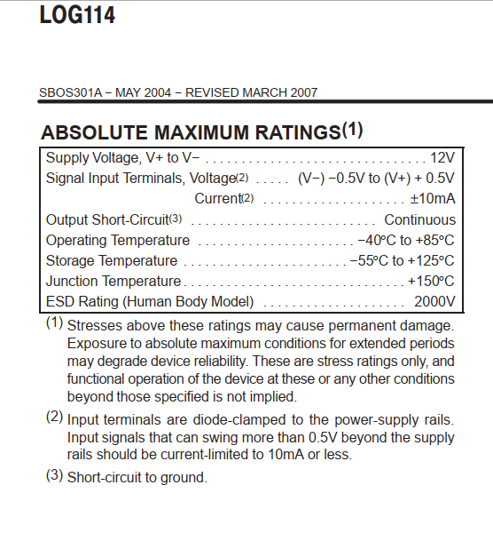
    the absolute maximum ratings are just for fun and can be violated if desired?? Of course not! Yes, exceeding the absolute maximum ratings can damage the chip! Please read again the datasheet, especially footnote (2):

    You can use a current limiting resistor at the input of LOG114 to limit the input current to less than 10mA.

    Kai

  • Hi MMx,

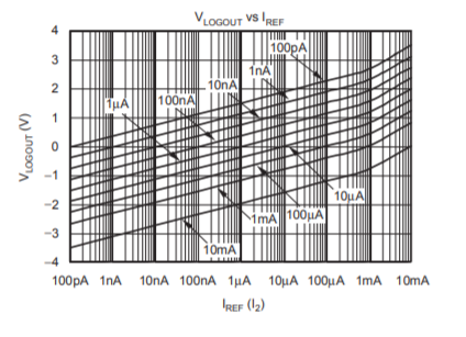
    As Kai pointed out the LOG114 absolute maximum input current is 10 mA and that should not be exceeded. The A1 amplifier output stage must sink the input current and as seen in the graph from the datasheet shown here the graph maximum is 10 mA. You will note that between 1 mA and 10 mA that the linearity of log response begins to depart from a staright line. This is due to heating of the logging transistor. If the current is increased beyond the maximum heating of the logging transistor can become excessive and there is the potential for damaging the transistor.

    The A1 and A2 output stage isn't designed to deliver much more than the rated 10 mA. Even if the input current is forced beyond 10 mA, their ouput stages will limit at some current level below 30 mA. The issue then becomes should the input current can be increased well beyond 10 mA, where is that current going if the output can't sink it? Likely, it is flowing elsewhere in the input circuit such as the input ESD diode path which is also limited to 10 mA. In any case, it is not a good idea to push the LOG114 input current beyond the 10 mA absolute maximum.

    If there is a concern that an input current source can develop more than 10 mA, then as Kai mentioned a series current limiting resistor can be added to the LOG114 input. Adding the resistor requires the input current source to develop a higher voltage for a given current level compared to when no resistor is present. It comes down to the ability of the input source current source's ability to deliver the required current up to the maximum, without running out of voltage compliance range. 

    Regards, Thomas

    Precision Amplifiers Applications Engineering

  • alright thanks. what will happen if the log114 is disabled (not powered) but the input sensor still delivers a current? I couldn't find anything regarding this matter in the datasheet.

  • If the LOG114 is not powered and you have a current source that can deliver 30ma there can still be trouble. If is close to a true current source it will put out whatever voltage possible to make 30mA flow which will find a path either through the input ESD diodes to the supply rails of the LOG114 and overvoltage the LOG114 or will turn on some other ESD clamps or other parasitic junctions.
  • Hi Tim,

    sorry I kind of mixed two questions here.

    Assuming I can get my sensor to remain in the range 0-10mA. Do you see a problem with attaching this source to an unpowered LOG114 circuit?

    Best,

    Michael

  • This should not be any issue provided you have TVS diodes on your supply rails. See link below:
    training.ti.com/ti-precision-labs-op-amps
    12. TI Precision Labs - Op Amps: Electrical Overstress (EOS
  • great, thanks