This thread has been locked.

If you have a related question, please click the "Ask a related question" button in the top right corner. The newly created question will be automatically linked to this question.

LMP7721: Unity gain stability of LMP7721

Part Number: LMP7721
Other Parts Discussed in Thread: TINA-TI, LMP7715, OPA376, TLV376

Hello,

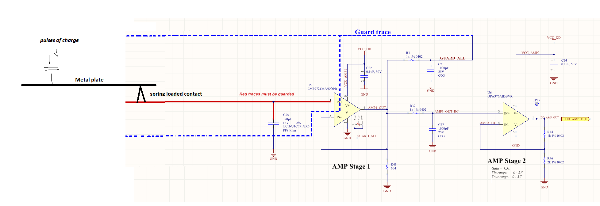
I have a few questions about the LMP7721:

1.  Is it unity gain stable?  The datasheet indicates pretty poor phase margin (~ 35 degrees) when Av=+1.  The small signal step response has 40% overshoot.  Anything that can be done to improve this?

2.  In unity-gain configuration, can putting a parallel R+C in the feedback path improve stability and reduce the overshoot?

3.  If I want to drive a 1.0 nF capacitive load on the output of LMP7721, I have to put a series isolation resistor.  What is the minimum value of series isolation resistor required?  (datasheet gives no information about open loop output impedance of the amp)

4.  All of the guarding examples in the datasheet show the guard driven from a different amplifier, not from the LMP7721.  Can the LMP7721 output itself be used to drive the guard trace?  (using some series resistance to isolate the LMP7721 from the capacitance of the guard trace, of course).  Why is this approach not shown in the datasheet?

Thank you, TI.  Other than these concerns it looks like an amazing part.

-Mohan

  • Hi Mohan,

    yes, the LMP7721 is unity-gain stable. And yes, the phase margin is very small. But nevertheless the LMP7721 can work as voltage follower and can drive capacitive loads, provided a careful phase lead compensation is carried out to restore the phase margin. The following circuit could be used to drive a capacitive load of 1n.

    The first plot shows the step response. The second plot demonstrates the frequency response and the third plot finally gives the result of a simplified phase stability analysis:

    So, this circuit should work stably.

    Of course, a simple scheme with isolation resistor can be used as well. But I wouldn't use an isolation resistor smaller than 47R:

    The open loop output impedance can be found by simulation with TINA-TI. I took 30R for the simulations.

    To your last question: I think that the LMP7715 and not the LMP7721 is used for the cable driver has only to do with cost efficiency: The LMP7715 is cheaper than the LMP7721.

    Kai

  • Mohan,

    Please see my answers below:

    1.  Is it unity gain stable?  The datasheet indicates pretty poor phase margin (~ 35 degrees) when Av=+1.  The small signal step response has 40% overshoot.  Anything that can be done to improve this?

    Yes, it is stable but as you said it does not have much phase margin.  You may improve the stability and capacitive drive by using a double feedback configuration-see below link:

    https://training.ti.com/ti-precision-labs-op-amps-stability-1

    2.  In unity-gain configuration, can putting a parallel R+C in the feedback path improve stability and reduce the overshoot?

    This may help but it comes at the price of much lower bandwidth.  The best is to use an isolation resistor with a feedback capacitor from inverting input to output and feedback resistor from inverting input to right side of the isolation resistor (double loop configuration ).

    3.  If I want to drive a 1.0 nF capacitive load on the output of LMP7721, I have to put a series isolation resistor.  What is the minimum value of series isolation resistor required?  (datasheet gives no information about open loop output impedance of the amp)

    For an op amp like LMP7721, it's typically enough to use a small isolation resistor of 10-50ohm to drive 1nF load.  Use 10mV square waveform and verify the stability by looking at the small-signal overshoot (ideally less than 25 %)

    4.  All of the guarding examples in the datasheet show the guard driven from a different amplifier, not from the LMP7721.  Can the LMP7721 output itself be used to drive the guard trace?  (using some series resistance to isolate the LMP7721 from the capacitance of the guard trace, of course).  Why is this approach not shown in the datasheet?

    It is because the guard must be driven to a voltage present at the non-inverting input terminal and most op amps are used in a gain different than 1.  However,  in case of a buffer, you may drive the guard with the output but be aware that each 1 meter (1 yard) of coax  line has an equivalent capacitance of around 100pF.

    Also, please be aware that if you are truly concerned about IB leakage, you must use a triax guard - see page 20 of LMP7721 datasheet for details.

  • Hello Kai, many thanks.

    For my last question, I was suggesting to use the output of the *same* LMP7721, as its own guard trace. This would only work for gain=1 (buffer) configuration, of course. Do you see any problem with this?

    For example: Could I take your simple circuit with the 47 ohm + 1nF output network, and use the output of that to drive the guard trace? Please let me know if it could work.

    Lastly, I am still expecting to see some overshoot and ringing on the LMP7721 output. The overshoot in the datasheet appears to ring around 19 MHz. So if I make the RC filter corner frequency around 100 kHz, will that be adequate to attenuate the ringing that is passed on to the next stage amp?

    Thanks again, Mohan
  • Hi Marek,

    Many thanks. I got another helpful answer from your colleague Kai as well.

    My application is simply to use LMP7721 as a buffer.
    Based on your response, I am thinking of putting a 1K series resistor on the output, followed by 1nF cap to ground. Then this
    output is taken and used for the signal guard. Will this be OK, or is 1K resistance too high of a source impedance to use for a guard ?

    This RC also has a time constant that (I think) should filter the overshoot and ringing which comes out of the LMP7721. Then I can
    pass this "clean" signal to a second amplifier (I am thinking OPA376) to implement a gain of 2 scaling.

    Please let me know what you think of this idea.

    Thanks,
    Mohan
  • Hi Mohan,

    Our applications engineer who covers the LMP7721 is currently on travel right now. I will provide some preliminary answers and when our other engineer returns this coming week he should be able to elaborate.

    1. Is it unity gain stable? The datasheet indicates pretty poor phase margin (~ 35 degrees) when Av=+1. The small signal step response has 40% overshoot. Anything that can be done to improve this?

    Yes, the LMP7721 is unity-gain stable. However, its phase margin degrades quickly with increased capacitive load. Figure 17. Open-Loop Frequency Response Gain and Phase response shows less than 45 degrees of phase margin with a 20 pF load. That phase margin should be adequate for unity-gain applications provided the load capacitance is minimized.

    2. In unity-gain configuration, can putting a parallel R+C in the feedback path improve stability and reduce the overshoot?

    It is best not to place resistance in the feedback loop for a unity-gain buffer. Phase shift is introduced into the loop by the feedback resistor in conjunction with the op amp's input capacitance and this reduces the phase margin. Adding a capacitor across an added feedback resistor can help, but without an input resistor it may be difficult to get the desired phase cancellation created by a lead-lag network.

    3. If I want to drive a 1.0 nF capacitive load on the output of LMP7721, I have to put a series isolation resistor. What is the minimum value of series isolation resistor required? (datasheet gives no information about open loop output impedance of the amp)

    Your point about not having the open-loop Zo is indeed correct. Not having that information makes it difficult to suggest a minimum Riso value. I suspect a resistor of a few hundred ohms would suffice, but the actual minimum may be lower.

    4. All of the guarding examples in the datasheet show the guard driven from a different amplifier, not from the LMP7721. Can the LMP7721 output itself be used to drive the guard trace? (using some series resistance to isolate the LMP7721 from the capacitance of the guard trace, of course). Why is this approach not shown in the datasheet?

    I don't know if this can be accomplished in the manner you propose. We will have to research this more.

    Regards, Thomas
    Precision Amplifiers Applications Engineering
  • Hi Mohan,

    I think this is a good moment to show us a schematic of your planned circuit...

    Kai
  • Mohan,
    A stability of the system is determined by the small-signal overshoot directly at the output of the amplifier and NOT on the right side of the isloation resistor. If you are driving high impedance or are not concern with the gain error, you may just use a buffer followed by the isolation resistor ( no need for double loop) to drive guard of the input line. Btw, capacitance of the guard may be just enough to filter out the signal before it's passed to the second stage so there may be no need for 1nF output cap. If you have any more questions, please show your proposed schematic so we better understand what you are trying to do.

  • Hi Kai, Marek and Thomas (thanks for all your replies, not sure who to address this to?)

    Attached is a circuit drawing of what I am proposing to do.  You can assume the power rail is 3.3V.

    I need a second stage amplifier because the LMP7721 is not Rail-to-Rail output.  I chose OPA376.  Is this a good choice?

    It is driving a 12-bit SAR ADC.

    The GUARD trace is derived from the LMP7721 output through a 1K/1000pF RC filter.  I am using the 1K to isolate the LMP7721 from

    the capacitance of the guard trace.  I added 1000pF because this forms a nice filter which should hopefully eliminate any overshoot that appears in the LMP7721 output.  I use the same RC filter between STAGE 1 and STAGE 2 circuits.

    The 604 ohm load is based on the LMP7721 datasheet, where the amp seems to show better stability with some kind of output load.

    Please let me know what you think.

    Thanks and Regards,

    Mohan

  • Mohan,

    What you propose should work BUT if the input signal is dynamic in nature and you are concerned about the input leakage current, I would remove C21 and lower R31 to avoid long RC delay causing the guard voltage to lag the input voltage resulting in a higher average leakage current - see below.

    And if your input signal is dc or low frequency, I would drive the guard with the same RC fed to second stage - see below (you may adjust C27 1000pF to 610pF to account for 390pF guard capacitance).

  • Hi Marek,

    Thanks for the reply and suggestions.  My input signal is not very dynamic.  You can consider my signal source to be a current source, it is outputting step function pulses of current every 200 milliseconds or so.  I am accumulating each current pulse on the 390pF capacitor and then taking ~100 milliseconds to measure it.  During that 100 milliseconds I do not want the current to leak off the capacitor, therefore the guard trace.  Please let me know if you think my original circuit will work for this case.

    I am unclear what the advantages are of your second drawing, i.e. taking the guard trace from the signal going to the 2nd stage amplifier.  I separated it into two RC branches so I could select a different RC time constant going to Stage 2 if desired.  Is there a disadvantage to this approach?

    Also I do not understand how we can reduce 1000pF-> 610pF.  Observe that the 390pF is not actually connected to my guard trace; the guard trace is surrounding it, but not connected.  So how can you subtract the 390pF from my original 1000pF?

    Thank you,

    Mohan

  • Mohan,

    If you apply step pulses every 200ms, and wait long enough for signal to settle before 100ms reading time, then you don't care about inverting input lagging behind and if so why to have two 1k||1000pF RC filters? How about just driving the guard with the same output as you drive the second stage, thus eliminating need for R31 and C21.
    As far as you last question goes, I mistakingly thought that C25 represents input guard capacitance. Nevertheless, there is coax line capacitance between signal line and guard, of around 100pF per meter, that adds to the total capacitance driven by the output of LMP7721 that should be subracted from 1000pF if you want to get output filter corner frequency right at f=1/(2∏RC)=1/(6.28*1000*1000e-9)=159kHz.
  • Hi Marek,

    Thanks. I guess I wanted some flexibility to set different time constant for the guard driver and for the second stage amp. I understand I can combine the RCs if I want to. But do you see any technical problem with my proposed circuit, (other than the issue that I might be using an extra RC circuit) ?

    Thanks again for the advice.

    Mohan
  • If signal is slow enough, I don't see an issue. But it is puzzling to me why would you want to have ANY extra delay in driving the guard line.  Having said that, you may need 100-200ohm in series with output to assure stability of driving the guard (you never said how long is the coax line).

  • Hi Mohan,

    a guard makes only sense if it is driven by the guard driver as low ohmically as possible. Stray capacitance and the guard resistance form a voltage divider and the higher the guard resistance is the worse the mains hum can be suppressed:

    That's why even in PH and ECG amplifiers the guard is driven very low ohmically. The guard resistance must only be high enough to sufficiently isolate the load capacitance from the guard driver output, in order to not erode the phase margin too much.

    Kai

  • Hi Marek,

    OK thanks.  Let me explain a bit more.  I thought the 1K/1000pF is a good idea because if there is any overshoot and ringing on the LMP7721 output, I do not want that to couple back to the guarded trace, and maybe cause oscillation (through positive feedback).  So I am trying to damp the LMP7721 output a little bit, to reduce ringing, before driving the guard trace.  Does that make sense?

    Also... there is no coaxial line.  The input to the circuit is coming from a metal plate which is located nearby.  This metal plate forms part of a capacitive sensor.  We are picking up pulses of charge on this metal plate.  These are then partially transferred to the 390pF capacitor which forms a capacitive divider.  Here is a more complete drawing of the input stage:

    Does this make more sense?

    Unfortunately I am unable to surround the metal plate with a guard.   We may have problems with ambient 60 Hz pickup, but I am not sure yet.  Possibly the 390pF capacitor will help minimize this.

    Thoughts?

  • Mohan

    This thread has been idle for quite a while. Were you able to resolve your issue? If not post another reply below.

    Thanks
    Dennis
  • Hi Dennis

    Thanks for the follow up.  I was waiting for a reply from Marek on my last comment.  Following that we should be able to close the thread pretty soon.

    Can you ping Marek for me?  Thank you.

    Thanks,

    Mohan

  • Mohan,
    The whole idea behind the guard is that it follows the input signal as close as possible so there is no net charge being diverted to charge/discharge guard to input trace capacitance - any such diversion of the charge will cause an error especially since you rely on the ratio of capacitive divider and thus you want to avoid any transfer of stray charge between the red trace input signal and its guard. Adding filter at the output may decrease the overshoot but increase a time delay between the input and its guard so you better off removing any filter driving the guard.
  • Three quick things to consider.
    1) LMP7721 SPICE macromodel on TI.COM matches the real silicon for open loop output impedance, Aol and other datasheet curves and parameters.
    2) In addition consider downloading the free SPICE simulator from TI, TINA-TI at:
    http://www.ti.com/tool/tina-ti
    By building and simulating your circuit in TINA-TI many problems can be avoided before building it in the real world. If you have problems once the circuit is built in TINA-TI feel free to post the schematic from TINA-TI on the E2E Forum for further assistance.
    3) Look at TLV376 datasheet Section 7.3.4 Common-Mode voltage range.