This thread has been locked.
If you have a related question, please click the "Ask a related question" button in the top right corner. The newly created question will be automatically linked to this question.
Hello!
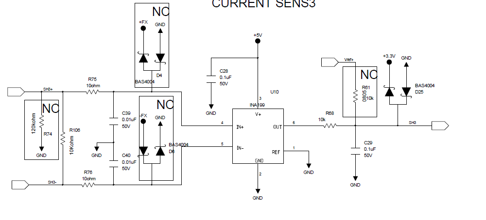
I am using INA199A1DCKR for DC current monitoring application on 48V line (low side sensing).
Previously I have tested (rigorously) prototype boards incorporating below design.
After prototype validation I replaced R75, R76 (10 ohm) resistor to ferrite beads and added a capacitor (0.1uf) across IN+, IN- pins.
But in the modified boards I received; while testing the circuit was functioning properly and correct current readings were measured. But suddenly the output of INA199 became zero.
I am using a 200/50 mV shunt and current through the shunt at the time of failure was ~25A (resistive) and was stable.
Also, I am using 2 separate circuits for measuring current through 2 different shunts and both went dead at the same time. And this happened in 2 separate boards (In total I blew up 4 INA199's but still the reason is unknown)
While measuring resistance between IN+, IN- pins and ground I observed that in working boards it is ~400kohms but in the faulty boards it came down to <10kohms and showing different values for different IC's.
And when the board is powered up only (without connecting the shunt connector) I see random mV value across the shunt connector pins.
Hello Mayank,
Thanks for reaching out on our form. So if I understand correctly, your device spontaneously stops working after power-up when the system is in steady state with a 25A load? Or does it fail during power-up? I do not see any immediate issues with your schematic. However, I suspect that your issue stems from using the A version (INA199A1)of this device as opposed to the B or C version (INA199B1 or INA199C1). If the device is powered on too quickly, such as from a battery which can immediately dump a lot of charge, the ESD structures in version A can potentially have issues that lead to slow degraded performance or the device spontaneously not working. Thus I would recommend replacing your version A devices with the B or C versions and rerunning your tests. If afterwards you still run into device failures, let us know and we will try to determine what else could be causing your device to fail.
Hello Patrick,
Thanks for prompt response. In one of the board device stopped working while the system was in steady state whereas in another board it showed wrong values after power up. Both the boards were only 2 days old and they were working perfectly a day before. In my schematic components which are mentioned as NC are not mounted on the board. Also I am powering up using an AC/DC module which builds its power slowly (nearly 20 secs to reach 48 VDC)
These are production lot boards and failure at this stage will lead to lot of issues. Also, is it guaranteed that using B/C version of devices will assure fail-safe operation? Because in prototype boards A version worked perfectly fine without any failure. However, I have ordered samples from TI for B and C versions.
Can you suggest some protective methods which I can connect in wire harness (as I cannot change IC in present lot) to improve the immunity of device?
Also I have read your replies in other posts as well regarding failure of INA199A version of IC's due to ESD latch up. If there is some inherent problem with silicon structure of INA199A version of IC's then I suggest that TI should discontinue it or at least mention 'Not recommended for New Designs' in the datasheet; so that people can opt for B/C version of device from starting only. As they are in similar price range; I think that will be more sensible thing to do.
Mayank
Hello Mayank,
Sorry about the delay in my response. As your devices are slowly powered up and remained powered, you should not have issues from power-up. Does your SH3- connect directly to GND? Do you have split ground planes? Could you check your input bias current?
It looks as though you already have included board space to include shottky diodes for protection. From some tests we performed here documenting various ESD suppression methods, we found TVS diodes to be the best. However, throughout the internet there appears to debate as to whether shottky diodes or TVS diodes are better.
As for the “Not Recommended for new Design” comment, great Idea! I am passing the suggestion along to our management.
Hello Patrick,
As I am performing low side current sensing, my SH+ and SH- both are connected to a shunt which is connected to -ve bus bar (GND).
I have a LVD (low voltage disconnect) contactor on negative line also (sensing is prior to LVD). This LVD contactor is actuated by my board itself after sensing low voltage levels.
I have observed that whenever I disconnect the LVD; a -ve going common mode noise is seen in both SH+ and SH- line. Amplitude of this common mode noise is ~1V on negative side for a period of 25-30 ms.
Allowable limit for -ve going voltage on INA199A1 is 0.,3V and is 0.1V on INA199B1 and INA199C1. So, I am not sure migrating to B/C series can resolve my problem (if not make it worse).
The provision for TVS was on my prototype boards but unfortunately I have removed those in final boards.
Also the tracks for actuation of LVD contactor (+48V and GND) are passing near by from my SH+ and SH- connector.
I tested a lot of combinations on board like using TVS externally but that is only clamping the -ve going voltage. I am not able to determine exactly why or from where this noise is being picked up by SH+ and SH- lines. (I cut tracks on PCB also and try routing it externally through wires).
But when I give GND directly to LVD contactor from -ve bus bar and only use +48V through my board (to control actuation of LVD), the noise surprisingly disappeared. But still I am not much confident about this work around as how reliable it is; or will it work fine at site after dispatch.
Can you suggest a way out off this or suggest any other robust IC / mode of sensing which I can implement in next revision.
Regards,
Mayank Shukla
Hello Mayank,
I have consulted with my team and found that one of my colleagues did document some methods to deal with negative transients here. With regards to using a different device, I would recommend INA240, INA282, or the LMP8640HV. If you are not really concerned with low current measurements, then you might also consider the INA193-198 and INA200-208. Out of all of these, I would expect the INA240 to be the best.