This thread has been locked.
If you have a related question, please click the "Ask a related question" button in the top right corner. The newly created question will be automatically linked to this question.
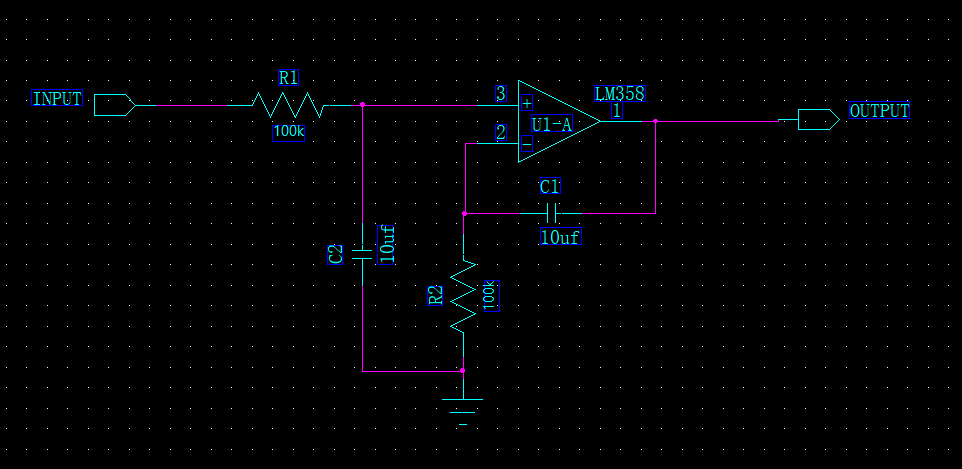
I test the intergrator design diagram of LM358. The input is 5V DC.
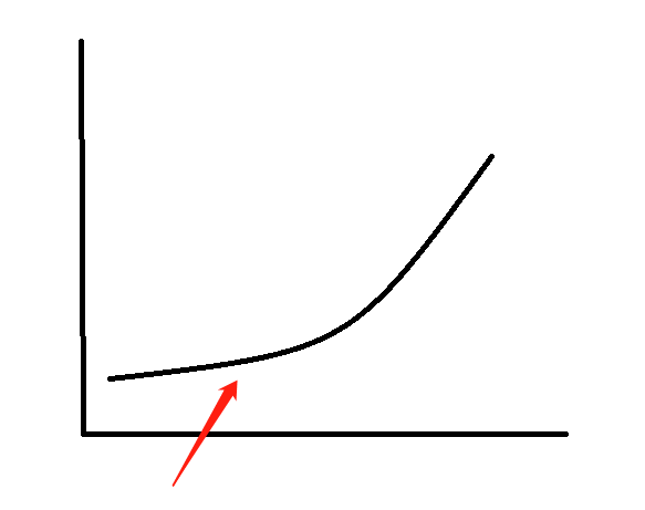
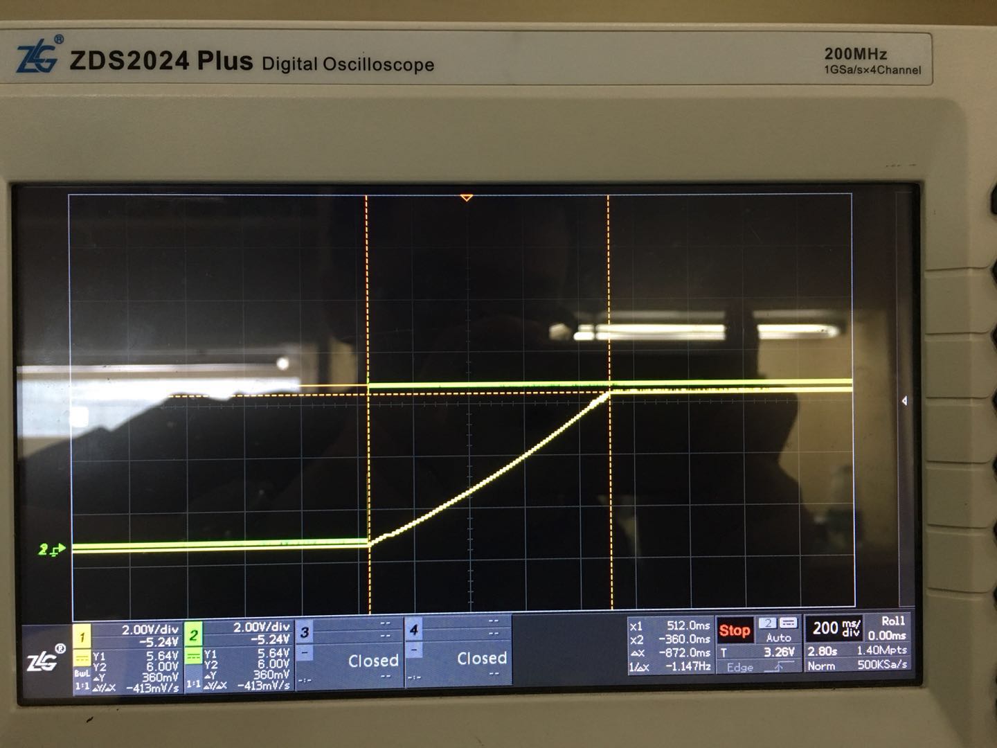
But as show below, the output of amplifier isn't a linear line, and the max output voltage is about 4.3V only.
I don't know why?
As in simulation by multisium, the ouput is a linear line and it's max output can be 5V.
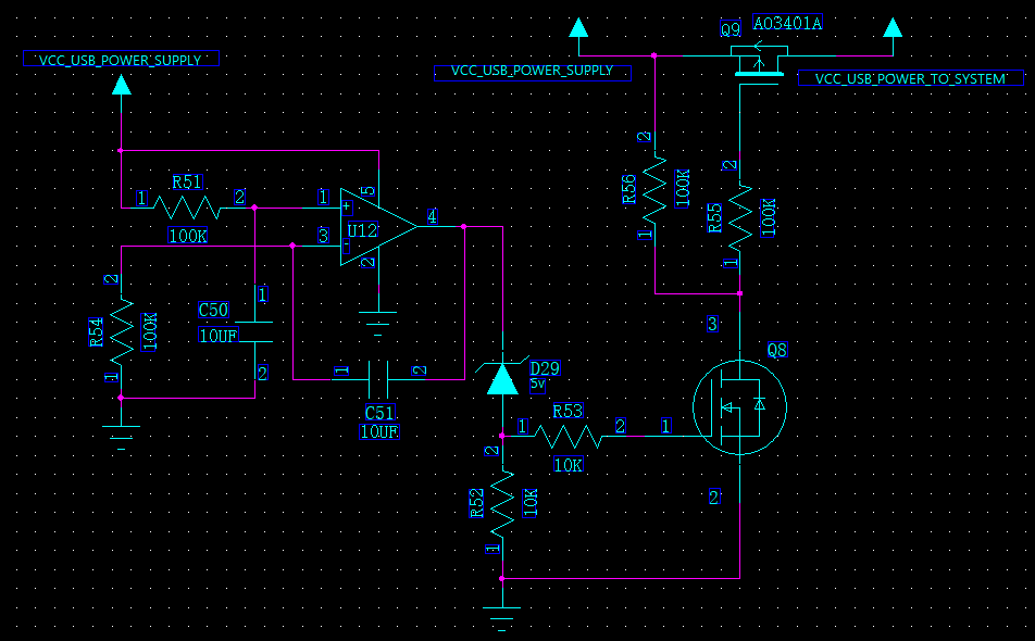
The design diagram:
The shape of output line:
Hello User,
The LM358 output only goes to about 3.7V with a 5V supply. The input range is also the same.
Is your waveform linear from 1V to 3.5V then becomes distorted?
Try TLV9002 instead, it has rail to rail input and output.
Thanks for your reply,
I design a board ,there were two different ways of my power supply.
The different ways is Battery Power and USB Power.
Normally, the user can use battery power. As time goes on, the Battery may inter low power mode. User can use USB power to supply the system when the battery in low power mode. I want to design a diagram that it can restart system when a USB power use to replace the Battary power. In order to make sure system restart, I design the digram like this.
(The battery power would be turn off when USB be used. And the changing-over diagram I haven't post.)