This thread has been locked.

If you have a related question, please click the "Ask a related question" button in the top right corner. The newly created question will be automatically linked to this question.

TINA/Spice: Op-Amp Selection for increased phase margin in improved howland current source

Other Parts Discussed in Thread: TINA-TI, LME49600, OPA4192, OPA192, OPA541

Tool/software: TINA-TI or Spice Models

As spoken about in a previous question HERE

I am trying to compensate a howland current source that must be able to drive a wide range of coils with an inductance range of 0 to 100mH and resistance of 0.1R to 500R, lowest natural frequency around 100Hz.

I also understand how various Op-Amp DC performance characteristics affect the accuracy of the output.

I understand to some extent the time constant of the coil, and the supply rails will limit the possible bandwidth.

Assuming those are fixed, what are the key AC parameters I should be looking for when selecting an Op-Amp.

  • Hi Hugh,

    I'll move this post to more apt forum. For opamp specific, you want to choose "Amplifiers Forum".

    Herman
  • Hello Hugh,

    The design of an Improved Howland Current Pump is more straightforward when driving a purely resistive load. Certainly, the power op amp ac concerns mostly come down to the slew rate and related Maximum Output Voltage Swing vs Frequency, the large signal bandwidth and large signal transient response.

    The parameter concerns grow as the load moves from being purely resistive to complex. The issue mainly being one of maintaining sufficient phase margin and keeping the amplifier stable when driving a complex load impedance. The power op amp itself exhibits a complex open-loop output impedance (Zo) that exhibits different R +/-jX characteristics in different frequency regions of its operating bandwidth. Coupled with the complex load impedance (ZL) it is easy to run into combinations where the phase margin goes to zero and the power op amp becomes unstable and oscillates.

    The ZL range that you propose of 0.1R to 500R, plus 0 to 100mH, is very wide. The impedance can be highly resistive at one end, or mostly inductive at the other end. Compensation can be developed if the power op amp Zo and a fixed ZL are known, but I suspect that it may be quite difficult to derive a compensation scheme that can assure sufficient phase margin under all of the proposed output load R + jXL conditions.

    Once you have more of an idea of how you want to set up the Improved Howland Current Pump circuit and what power op amp you are considering you may want to run your ideas past us.

    Regards, Thomas
    Precision Amplifiers Applications Engineering
  • Thanks Thomas

    The range probably isn't as bad as it looks at first glance, the minimum resistance for when loads are inductive would be about 20 ohms, anything less than that would be purely restive loads.

    There is a bit more detail in a previous question e2e.ti.com/.../739959 but a quick summary of the circuit is that I am using an LME49600 as my power stage, and I had been using an OPA4192 to close the loop, as well as to buffer the output voltage on the downstream side of the current shunt resistor. I was planning on using a matched resistor network for the feedback network (all 20k) and a 10ohm shunt.

    I was looking at if the compensation can be relaxed by replacing the OPA4192 with a different amplifier. From the analysis I believe that an op-amp with a higher open loop gain (at least at higher frequencies) helps with this. Is this correct, and if so is it simply a case of looking for the op-amp that meets my DC requirements and has the highest GBP.
  • Hi Hugh,

    can you show us a schematic?

    The coils, which self capacitance (winding capacitance) do they have?

    Kai
  • Hello Hugh,

    I am sure you are aware that stability will have to be analyzed taking into account the OPA4192 op amp, the LME49600 buffer amp and the complex load impedance. Each circuit portion has its on gain/phase that must be known across frequency. For the OPA4192 and LM49600 the open-loop gain/phase (Aol) and open-loop output impedances (Zo) are needed. Switching the OPA4192 with a higher bandwidth op amp may, or may not, affect the phase margin as one might like. It really comes down to the Aol and Zo characteristics over frequency of both amplifiers in the loop.

    The OPA4192 is a precision op amp and its simulation model accurately mimics the Aol and Zo of the actual device in a Spice simulation. The LME49600 is produced by one of TI's audio products divisions so I am not sure how closely its simulation model comes to mimicking the true Aol and Zo characteristics of the device. The notes, internal to the Spice model documentation, tends to indicate that the model only models a small number of parameters. You know the characteristics of the load and that will certainly be needed for an accurate analysis.

    Support far the various TI E2E forums will be minimal across the holidays. If you do submit more information about your application there is a high probability that it may be a couple of weeks before the discussion resumes. Thanks for understanding.

    Regards, Thomas

    Precision Amplifiers Applications Engineering

  • Thanks Thomas, would be able to elaborate more on what effect the model for the LME49600 will have (in terms of being simplified)

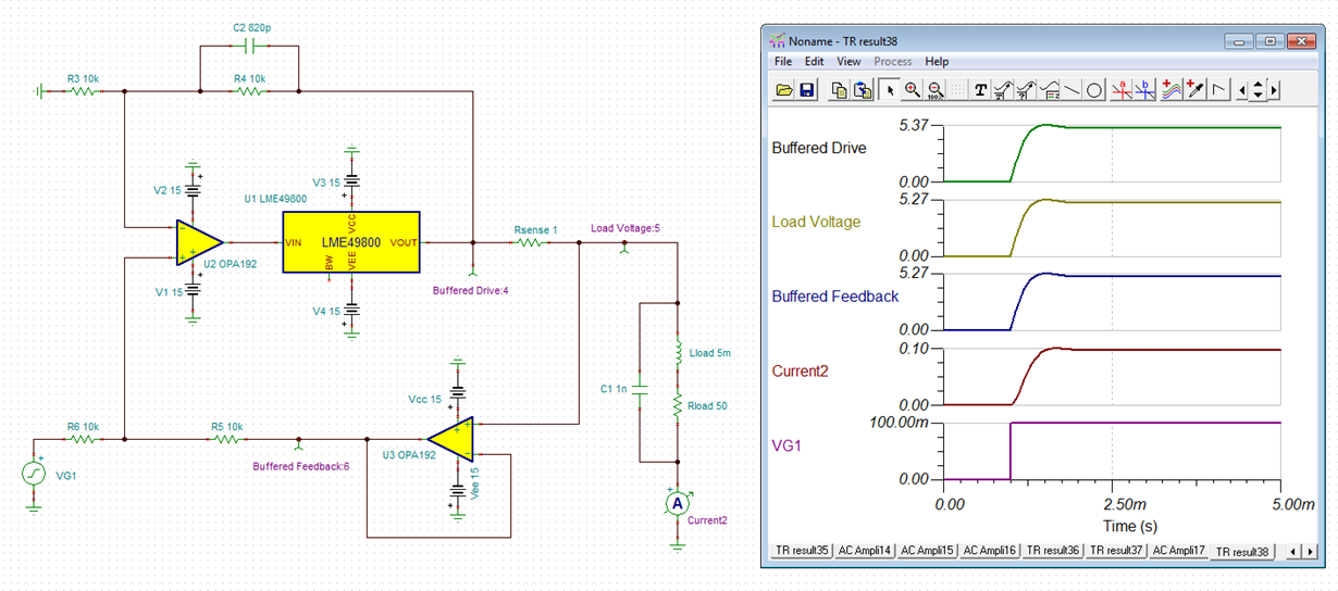
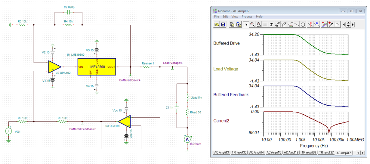
    Below are the two circuits that I am simulating.

    DC & Transient Performance.

    AC Open Loop Analysis

    As a side note the model for the LME49600 Seems to show up as the LME49800 in schematics, not sure why though.

  • Hi Hugh,

    again, the coils you want to drive, which self capacitance (winding capacitance) do they have?

    Kai
  • Measuring a few coils I have on my desk I get a range between 0.2uF and 2uF when measured at 1kHz which is admittedly a chunk more than I expected.

  • Hi Hugh,

    only knowing very little about your application and under the assumption that the LME49600 and OPA192 must be used, I would start with this circuit:

    hugh1.TSC

    C2 is a phase lead capacitance which restores the phase margin of the overall circuit. Without this capacitance the circuit will become unstable.

    The disadvantage of this scheme is, that the signal has to run through three OPAmps and that each OPAmp adds its propagation delay time and phase shift. Because of that, a rather high C2 must be chosen to keep the circuit stable. The result is a very limited overall bandwidth. A better approach were to use only one single high output current OPAmp and to build a classical Improved Howland Current Pump. TI has lots of very nice high output current OPAmps.

    By the way, why not omitting U3? It isn't really necessary.

    Kai

  • With this circuit we do not need a super high bandwidth 1-2kHz corner frequency would be acceptable, we do however need high accuracy. U3 was used to remove current error from the output due to current flow through the feedback path, it also separates the effect of rs from the ratio of R3,R4,R5,R6 which is required to have a low output impedance.

    As for why I am using one control stage and one power stage, I couldn't find any op-amps TI or otherwise with suitable characteristics. I require an output drive of up to 200mA which cuts options significantly, as does requiring a low offset voltage take OPA541 for example which has a 10mV max offset which would equate to a 10mA offset, compare to 40uV for the OPAx192 equating to 40uA

    The voltage divider before the buffer IC is to prevent saturation as the OPA192 is rail to rail and the LME49800 is not.

    As in my previous question, I have done some AC analysis, the point of this question was to more try and get some tips on what AC datasheet parameters I should be looking at to allow larger phase margin and or higher bandwidth. At the moment all I really know to look at is the GBP along with the magnitude in the open-loop gain plot.

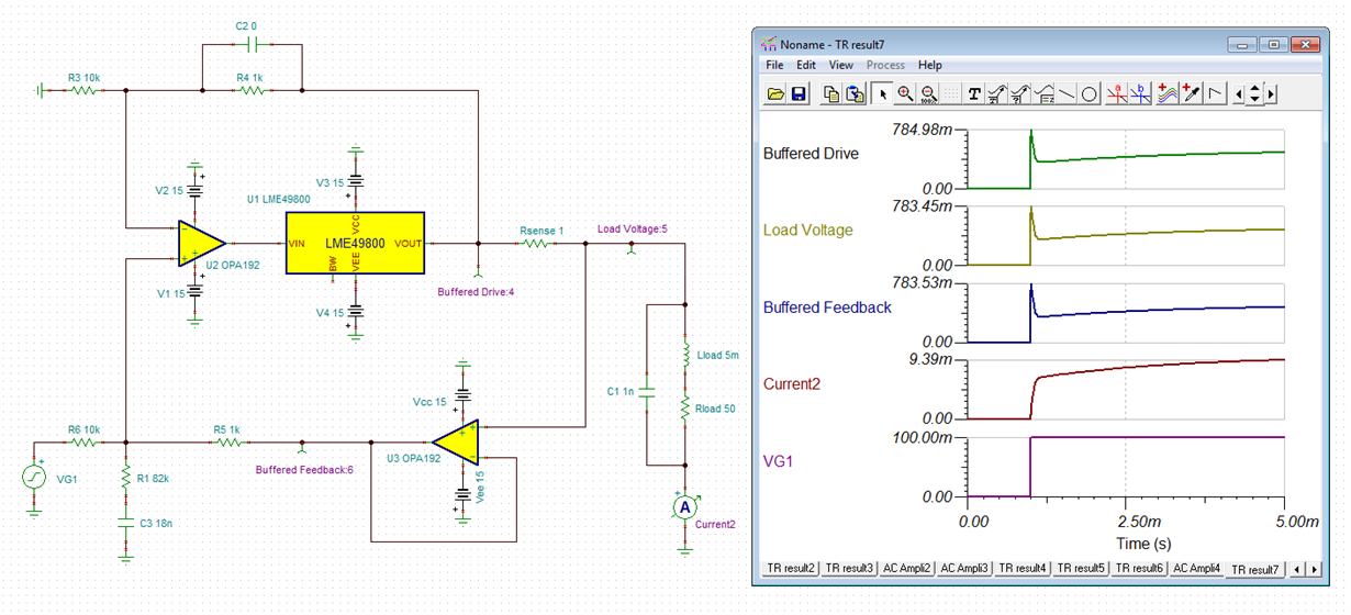
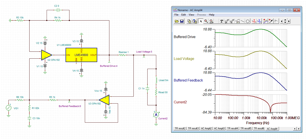
    As a side note from both simulation & real world testing I have found the best place to add stabilisation is an RC network at the non-inverting input or across the load.
  • Hi Hugh,

    with the 82k and 18n "snubber" the frequency response looks rather wavy. And the step response shows a scary peak:

    Is this tolerable for your application?

    Kai

  • Hugh

    We haven't heard back from you so we assume this resolved your issue. If not, just post another reply.

    Thanks
    Dennis
  • I wouldn't see the step in voltage as scary as it is the output current that we are interested in, and the higher the voltage the faster the current is going to be ramped up, likewise the Current bode plot is the key one of interest to us, and the peaks in voltage make sense to me as to drive the inductor at a higher frequency will require a higher voltage.

    Regardless of these stabilisation techniques, what I am after is what effect the op-amp has on the equation. What AC parameters should I be assessing when I select an Op-Amp other than pick some that have promising DC parameters and then try at random.
  • Hi Hugh,

    I would take an OPAmp which comes with a well fabricated model. And I would model the coils as accurate as possible. This will allow you to carry out a meaningful phase stability analysis.

    I think stability is a major issue in your application. And because of this I would not choose the fastet OPAmps available. The faster the OPAmp is the more difficult it gets to make the circuit run stably. An unity gain bandwidth of 1...5MHz should be sufficient, if your signal frequency range of interest is only 1...2kHz.

    Kai
  • Hugh

    Do you have everything you need for your circuit design? If you have additional questions just post another reply.

    Dennis