This thread has been locked.

If you have a related question, please click the "Ask a related question" button in the top right corner. The newly created question will be automatically linked to this question.

XTR106: know the XTR106 was damaged or work correctly

Part Number: XTR106

is it any way for test of XTR106?

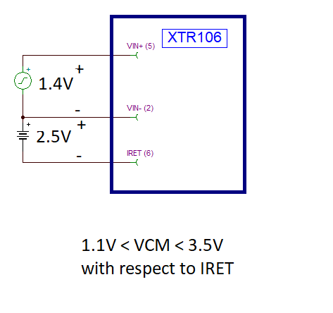
I give constant 1V between pin5 and  Pin2 and I put ampere meter between pin2 and pin3 of P1 connector but the current was zero! is it mean the XTR106 was damaged?

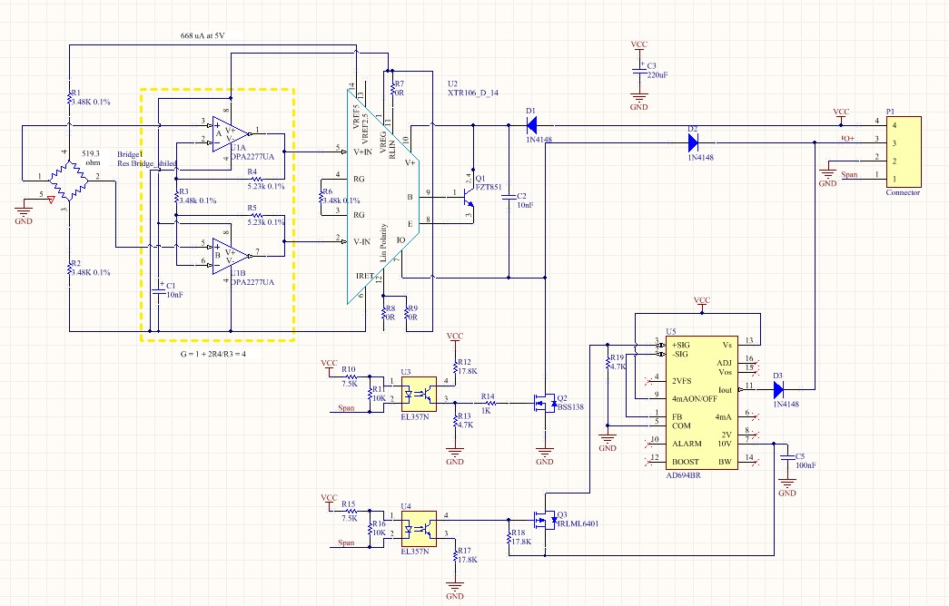
and the voltage between pin14,pin11,pin6 and ground (pin2 of P1 connector) is near Vcc=24V!!!

  • Hi Amir,

    When applying the test differential signal between pin (5) and pin (2), please keep in mind that there is a common-mode voltage range requirement with respect to IRET.  The allowed common-mode range is between 1.1V to 3.3V with respect to IRET. Also IRET must be allowed to float with respect to the loop ground.

    Can you connect the test signals as shown below, where a DC source connects between IRET and VIN(-) to set the voltage to +2.5V, and a second DC source between VIN(-) and VIN(+) sets the test voltage to +1V?  Please see below.  Please note, the IRET potential must be allowed to float with respect to the loop ground.

    Can you measure the  VREG voltage with respect to IRET?  Is the VREG voltage around 5.1V?

    Many Thanks,

    Luis 

  • Hi Amir,

    why are you starting a new thread?

    If you want to apply a voltage to the inputs of XTR106, then you must do this as shown in the datasheet. In particular, you must provide a current path for the input bias currents to pin 6 of XTR106.

    Kai

  • Hi Luis

    thanks for your helpful guide..

    I test by this method but the output current is zero!

    by your method i have about 2V between the VREG voltage with respect to IRET

    but by my circuit that i mentioned in below the voltage between Vreg and Iret is near zero

    https://e2e.ti.com/support/amplifiers/f/14/p/778707/2882521#2882521

  • Hi Luis

    thanks for your helpful guide..

    I test by your method but the output current is zero!

    by your method i have about 2V between the VREG voltage with respect to IRET

    but by my circuit that i mentioned in below the voltage between Vreg and Iret is near zero!

    ]

    is it means the XTR106 was damaged?

  • Hi Kai

    I do this but the results was same
  • Hi Amir,

    As suggested by Kai on the other forum thread, start with a fresh XTR106 device and external transistor.  Ensure that the sensor and/or driving circuit is referred to the IRET potential, and that the IRET is allowed to float with respect to the loop ground.  Also ensure the Rload resistor is present, wiring the circuit as described on the datasheet.

    Since you have another ongoing thread, please reply/continue the discussion on the thread below.

    https://e2e.ti.com/support/amplifiers/f/14/p/778707/2883062#2883062

    Many thanks,

    Best Regards,

    Luis

  • Hi Amir,

    To avoid having duplicate threads on the same topic, please reply and/or continue the discussion on the original thread below:

    e2e.ti.com/.../2883062

    Many thanks,

    Best Regards,