This thread has been locked.

If you have a related question, please click the "Ask a related question" button in the top right corner. The newly created question will be automatically linked to this question.

THS4522: Trying to select a TVS diode, or other input protection device, to protect input to THS4522

Part Number: THS4522
Other Parts Discussed in Thread: THS4552, THS4551

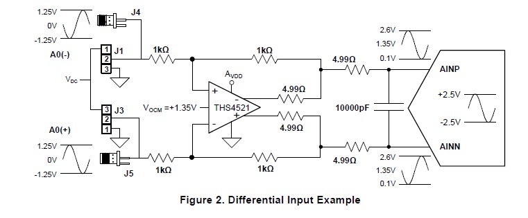
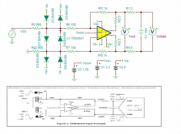
I am trying to protect the input pins to the THS4522.  I have fairly low level, differential signals going in, but want to protect to near the maximum rating of the THS4522.  I have not worked with TVS diodes before, so I am having difficulty selecting a readily available (Digikey) TVS diode.  I am also aware that I may need a resistor or two, like in Zener circuits, for this protection to work properly.  Would anyone be able to recommend a bidirectional TVS diode for this component?

If there is another input protection scheme, I would be interested to hear about this as well.  Thanks in advance.

  • Hi,

    Are you trying to setup an external ESD protection circuit? This device has ESD ratings of 1300V HBM and 1000V CDM.

    Here is maybe something that can help you. It lists some part numbers and has some design considerations.
    www.ti.com/.../slyt492.pdf

    Thanks!
    -Karan
  • Hi, I will take a look at the link. I was thinking of protecting the amplifier from a possible over-voltage situation from our source signal. I just want to protect the amplifier from, say, if our source acted up and somehow output 10V or 20V instead of our much weaker signals. I am literally just trying to protect the amplifier above it's maximum rated voltages. I think the input pin is rated to (VS–
    ) – 0.7 (VS+) + 0.7. So anything above that range I want to clip.

    Appreciate the advice and looking forward to hearing back from you!
  • Hi,

    robust TVS have high junction capacitances and can considerably slow down your apllication. I would clamp the source signal to the supply rails of THS4522 by the help of low capacitance silicon or Schottky diodes. Eventually the current through this clamping diodes must be limited by additional series resistors and eventually the supply pins of THS4522 must be protected by TVS against overvoltages. And if the power supply can't accept reverse currents I would add series diodes in the supply lines of THS4522.

    In any case your protection devices should sit outside of the feedback loop of THS4522. Do never mount them directly at the input pins of THS4522. This would add undesired stray capacitance to the inputs and would erode the phase margin resulting in instability.

    Kai
  • Hi, many folks use the BAV99 for this kind of thing, if you have a ckt I will show you how to do that.- parts like this, I think they might even come as quads

  • Hello all! Thank you for your feedback. It is easy to go down the rabbit hole for TVS literature! I am still trying to evaluate options and determine the correct way forward.

    I wanted to add some clarification. Between the two input pins of the THS4522 could be as much as 9Vpp. However, since this is differential signaling, each input pin would see half of that, meaning, a 4.5Vpp (centered at 0V) signal on each input (and obviously 180 degrees out of phase of one another).

    I have found some very low capacitance TVS diodes geared towards Ethernet comms, so I am hopeful that something like this would work in my application (hundreds of kHz), even if I am forced to place it at the input of the diff amp.

    The biggest issue I *think* I have now is weeding through all of the possible contenders for TVS diodes. I want to ensure that after a signal of 9Vpp (between the two input pins), that I am clamping to this voltage or very close to it. Based on this info, does anyone have any candidate TVS diodes, or rules of thumb in help me down-select my choices?

    Another issue I'm having is how the excess current (voltage) is bled off. The THS4522 is operating on a single 5V supply. Would the TVS diode go between the two input pins or would each TVS diode have to connect between an input pin and the diff amp's ground, to bleed off the excess signal? I am trying to use a single bidirectional TVS diode but not sure if that is the best path forward.

    I really appreciate the help. This is my first time working with TVS diodes and there is a lot of good info out there, but I am starting to question everything.
  • Morning, again a schematic or TINA file would be make this more fruitful
  • Attached is a sample schematic of which the circuit I am trying to find a TVS diode for was derived from.  Any help is greatly appreciated!

  • Ok, thanks - points,

    1. The THS4552 is the much upgraded version you should probably use if you can. Much better noise and DC terms.

    2. Having those input resistors is where you can limit the fault currents with protection diodes.

    3. The attached word file shows some suggestions - you don't have to use the BAV99 but many do. 

    4. TINA can't simulate the macromodels going in and out of overdrive - at least I can't get either transient or DC sweeps to not crash.

    Protecting THS4522 or THS4552 from overdrives.docx

    And then a sim file, can only attach one at a time, but this will get you going perhaps - dropping in the updated 2016 THS4522 model worked a little better, but not completely. Used the single channel THS4551 model, but you can drop in the THS4522 if you want. 

    Simple gain of 1 THS4551 with protectionTSC.TSC

  • Wow, thank you for all the great info. I read through the word doc...might need to read through it again a few more times to comprehend it all :)

    I will investigate the THS4552. It's actually not my design we have been discussing, but a teammate's design. I am trying to help him with determining protection circuitry for his board.

    I'll continue to do some research on my end, but welcome to any and all feedback by any who wish to participate in the conversation! I may be posting back here in a day or so...
  • Hi Michael,

    splitting the input resistances as shown in your scheme below is a very good idea. I usually do the same in my circuits.

    But I would make R6 and R7 a bit bigger (and R5 and Rg2 a bit smaller, accordingly) to better isolate the inputs of THS4551 from the diodes' junction capacitances. This would furtherly decrease the currents into the THS4551 as well. This can be helpful when it comes to latch-up issues (ESD, etc.).

    Please don't feel offended by these statements. I'm well aware, that you know much much more about these OPAmps. :-) It has cost me some overcoming to make this post...

    Kai

  • No problem Kai, you obviously have a lot of hands on experience also.

    In this case the resistor split is a judgement call - the larger input R is limiting common mode inputs beyond the supplies, the smaller 2nd one is limiting differential overdrive where actually it should not be possible to exceed the 1V Vdiff max quoted with the differential protection.

    I lean on the BAV99, but actually the currents here might be so low as to suggest a less robust device with lower C. If there were a similar two diode
    Schottky device with lower C that might be better.
  • Ok, I will admit that I am still a bit overwhelmed with all of the information and protection schemes out there.

    Here's my problem:  The input to the THS4522 should be no more than 4 Vpp on each input.  So +/-2 Vpeak on each input.  In reality, what we have is an 8 Vpp differential signal.  After that point is when distortion and clipping come into play (we've seen this in the lab with our testing).

    Since my coworker's PCB is limited on space, I was hoping that we could simply throw a bidirectional TVS at the input, since there's already some resistors in the loop that would help limit current.  The application does not exceed 500kHz, hence why we were hoping that a low-capacitance TVS would do the trick and not affect the performance of the circuit.

    Another thing I am confused about is what ratings I should be looking for.  Am I correct in thinking I am looking for, IDEALLY, a bidirectional TVS diode with Vbr = 4V?  Or is it 8V?  I am assuming 4V as the theoretical graphs I've seen indicate that Vbr exists, for a bidirectional TVS, in both positive and negative voltages.

    I really do appreciate all the advice thus far...I humbly ask you to continue sharing your advice with me!