This thread has been locked.

If you have a related question, please click the "Ask a related question" button in the top right corner. The newly created question will be automatically linked to this question.

XTR117: XTR117

Part Number: XTR117
Other Parts Discussed in Thread: XTR106, XTR111, XTR105

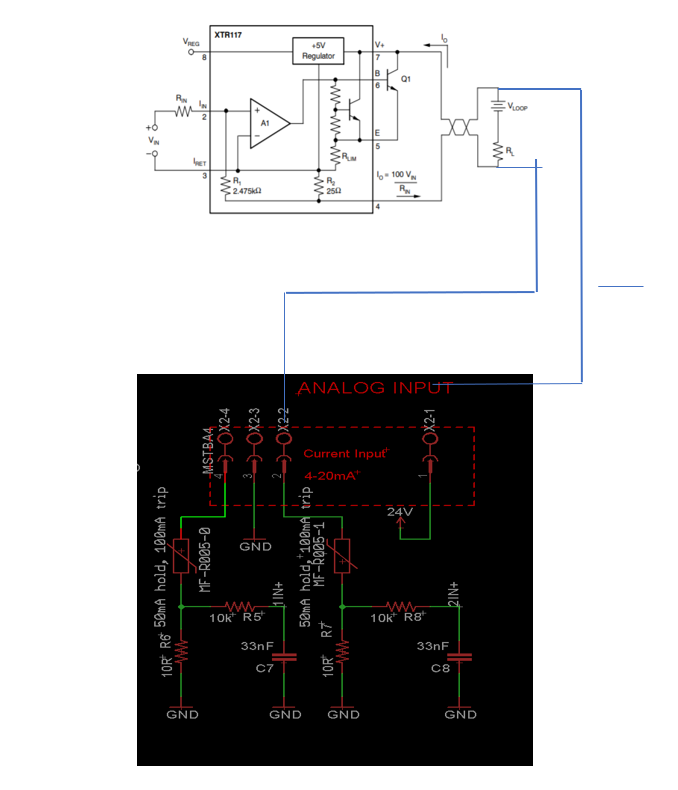
I am using XTR117  for an output of 4-20mA current loop transmitter, when we are connecting a resistor across Pin 4 and Pin 3 of XTR117IC and calclulating current, i am getting it in 4-20mA.

But as shown in circuit diagram attached, i have to power it using my board (already can be seen in circuit diagram attached),

But in this case we are not able to see any output in terms of 4-20 mA, across R7 this is what the main problem as we are not able to see the value when powered in loop.

We are giving 3.0 V on pin 2  through extrernal DC Supply.

please help with this.

  • Hi Ankur,

    don't use an external supply voltage to provide an input signal to the XTR117. Use the VREG pin instead. And insert a suited Rin. Pin 2 is a current input!

    And why would you want to mount a resistor between pin 3 and pin 4??

    More, where is your GND conection?

    Exactly wire the XTR117 as shown in figure 3 of datasheet.

    Kai
  • In our end design, we will be giving input to Pin 2 of XTR117 from DAC,

    Thus even if we use Vreg for now, we cant use that in our final design.

    All i am confused that how can i connect IRET so that while varying a voltage from 0-3.3V, when we check current through R7,

    Currently for testing the functionality of IC we are giving input from external power supply, and looping it with my external board which is having analog input, and all i want that my i can see the current vary through R7, but it is not happening.

    the circuit is attached below-

    A side is the input either from DAC but currently with external power supply

    is the external board, this is the actual board which gives 24 V to the loop and takes current input

  • Hi Ankur,

    what you plan will not work. You cannot feed the input of XTR117 with an externally supplied DAC. Please see this thread:

    e2e.ti.com/.../770353

    Kai
  • Thanks for the help, 

    As you mentioned we should not give direct power supply to XTR117, so now we used a potentiometer and gave it supply from Vreg and taken it's output to Iin pin 2, and connected GND of Potentiometer to IRET

    It is similar to the below circuit given in datasheet.

    But still not able to get any output

    Figure 1 - my circuit with potentiometer

    Figure 2-  as in datasheet

  • Hi Ankur,

    what potentiometer do you use? Remember that only less than 3.8mA is allowed to flow out of the VREG pin to keep the XTR117 in regulation. And don't omit the 10nF decoupling cap between pin 7 and pin 4, as shown in figure 3 of datasheet!!

    Kai

  • 500K potentiometer is being used, is it due to that, i am not getting the output?
    yes i am placing the 10nF capacitor b/w 7th and 4th pin
  • Hi Ankur,

    yes, add the 10nF decoupling cap!

    I suspect that you already have destroyed the XTR117. Take a fresh one and try again.

    Kai
  • Hi Ankur,

    Kai is correct. Let us know the results with a XTR117 swap. I will close this.
  • hi Sir,

    thanks for the help, i am getting the current in loop

    but now i am facing another issue

    i am using the below circuit for application of giving input of RTD to my circuit and getting 4-20mA loop output.The first one is from datasheet of xtr117

    and the second one is the actual one i am implementing.

    The issue which i am facing is that, 

    Please see A and B in below circuit

    when i am connecting B i am not getting any output in my loop, but when i am giving  a separate supply on my wheatstone bridge circuit, i am getting a proper output.

    i.e. when i am giving Iret to wheatstone bridge ground as well as my opamp ground, i am not getting any output.

    but i have not to do that in my actual design as it will be having just loop power of 24 V and not any other supply.

  • Hi Ankur,

    your PT100 bridge draws way too much current from the Vreg pin. Read the section "MINIMUM OUTPUT CURRENT" of datasheet of XTR117.

    One remedy is to use current limiting resistors in series to the bridge as discussed in the datasheet of XTR106.

    Kai
  • I tried your suggestion, 

    1) As per limiting resistors in XTR106

    tried it with 1.2K, 3.4K in both the case my Vreg drops to 4.9 V to 1.2 V and even XTR117 is also getting little bit heated.

    In my wheatstone bridge circuit my three resistors are 100 ohms and 4th one is from PT100

    2) Please refer the below image as well,

    in it when i am connecting point 2 i.e. ground of wheatstone setup with Iret no output  is coming 

    3) If we use external supply to my wheatstone, and common ground of wheatstone circuit and opamp ( even if i dont use XTR117) i dont get any output and if we dont do that commoning, we get output from opamp perfectly.

  • I tried your suggestion,

    1) As per limiting resistors in XTR106

    tried it with 1.2K, 3.4K in both the case my Vreg drops to 4.9 V to 1.2 V and even XTR117 is also getting little bit heated.

    In my wheatstone bridge circuit my three resistors are 100 ohms and 4th one is from PT100

    2) Please refer the below image as well,

    in it when i am connecting point 2 i.e. ground of wheatstone setup with Iret no output  is coming

    3) If we use external supply to my wheatstone, and common ground of wheatstone circuit and opamp ( even if i dont use XTR117) i dont get any output and if we dont do that commoning, we get output from opamp perfectly.

  • Hi Ankur,

    whatever you connect to the input side of XTR117 must be completely powered by Vreg (pin 8) of XTR117. When you want to connect external circuitry to the input of XTR117, you need to provide galvanic isolation as shown in figure 4 of datasheet. Take this figure serioulsy. It's no joke. And also keep in mind that only 3.8mA may be drawn from Vreg.

    Or you can take a non loop-powered voltage to current converter, like the XTR111, e.g. This converter is free from these restrictions.

    Kai

  • Sir,
    Thanks for all the help.
    i am using Vreg pin only, to supply.
    And as your suggestion, i was getting loop working fine.
    Sorry to confuse, but please see point 1 and 2 in my last reply to you.
    i am having trouble with that, i think i am not able to use that Vreg pin to supply to wheatstone.
    Please see point 1 and 2, sir.
  • Hi Ankur,

    I think the way you amplify the bridge signal is unsuited. You would need an offset to handle the cases "PT100<100R" and "PT100>100R".

    Kai

  • Sorry Sir,
    didnt get the offset thing,
    does that means, i have to use some other opamp or any other values in my wheatstone setup?
    Please if you could explain, would be great help, sir.
  • ankur.TSC

    R3 runs from 90R to 150R in the simulation.

    You should rework your circuit.

    Kai

  • Thank you so much sir for the help, but i am like trapped in this,

    attaching my another circuit and mentioned the current and voltages i am getting,

    please help with the changes i should make it to work.

  • Sir, 

    Please if you can help with my issue, would be great help.

  • Hi Ankur,

    when using a PT100 element you must limit the measuring current to 1mA. Otherwise you will have too much self heating. This means that the correct way to drive a PT100 element is to use 1mA constant current and not a constant bridge voltage.

    Have you thought about using the XTR105? This current transmitter supports the use of PT100 and provides constant current sources of 800µA.

    Kai
  • Thanks for the help sir, 

    I got my PT100 working with some changes in my wheatstone's resistor arrangement NOw our resistors are 10k,10k,100R and PT100, after that we were getting 5V and proper current.

    But now,

    Since we have to set our system according to above figure, 

    1) SInce our MCU draws 150mA current, how can we connect that in our whole arrangement so that there is no limit of current.?

    2) Can we common GND1, GND2, GND3 with IRET pin?

    3) or is there any other way, i can incorporate MCU in my design.

    and since XTR105 is costly, i cant use that in my design.

  • Hi Ankur,

    when using the XTR117 you cannot connect GND1, GND2, GND3 and IRET together. You will need to provide optical isolation as shown in figure 4 of datasheet of XTR117.

    In this case I would switch to the XTR111.

    Kai
  • As you advised to use XTR105,
    How will i get that, how will i will be setting my value of resistance at 4mA and at 20mA
    if i take my temperature range from 0 degree to 100 degree
    what equations will be used to adjust offsets?
  • Hi Ankur,

    it's explained in detail on pages 7 and 8 of datasheet of XTR105.

    Kai
  • Hi Ankur,

    We haven't heard from you in several weeks. Closing this thread now.

    -Tamara
  • As i was suggested to use XTR105, thus i am waiting for it to get delivered for testing.

    Please, if you could let this thread open.

  • Ankur

    We need to close this thread, but when you get the XTR105 and have a chance to evaluate it, feel free to post a reply here, or create a new thread if this one is locked.

    Regards
    Dennis