A related question is a question created from another question. When the related question is created, it will be automatically linked to the original question.
If you have a related question, please click the "Ask a related question" button in the top right corner. The newly created question will be automatically linked to this question.
LMH5401: Significant miscorrelation between LMH5401 Eye Height/Eye Width measurement results vs. TI LMH5401 ADS model simulation results for Signal Bit Rate 11.67 Gbps
Do you know what analog bandwidth you required to transmit your signal? Judging from the eye diagram it looks like this is a non-encoded signal running at the full 11 Gbps. In that case you will need a bandwidth approximately 5x that speed to get a reasonable edge rate on the signal. In this case that would be a 55 GHz device, which is quite a bit faster than the LMH5401.
Original question related to significant misscorrelation between lab measurement results vs. TI provided ADS model for ADS channel simulation
Please check TI ADS model and adjust it according to Lab measurement results.Please see details in the attached presentationAmp_model_Investigation_30.07.19_v2.pptx
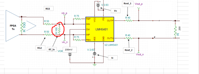
I do wonder about your terminations, If the FPGA output is 100ohm source, are those 50ohm series intended to be the termination at the LMH5401 inputs - if so, you don't need that differential 100ohm across the inputs. Just hurting BW.
On the outputs, each side is 50ohm including the internal 10ohm. The correct differential termination is 100ohm, not 200ohm.
Perhaps the piece you are missing is that the two input pins are virtual summing junctions and very low impedance -the 100ohm diff. does nothing but increase the noise gain reducing bandwidth.
Well it might, what do think the circled R is doing? It is not a termination element as the nodes are low impedance summing junctions for a wideband FDA.
Imagine for a moment you are driving a single ended inverting opamp with the input resistor set to 50ohms. Yes the input impedance looks like 50ohms since the inverting node is a virtual ground due to the op amp loop gain. Then, imagine adding another resistor to ground on that simple inverting op amp stage. You have not changed the input impedance or signal gain, just raised the noise gain bandlimiting the response from where it was - that is exactly the same thing that your 100ohm differential R in the circuit above is doing.
Coming back to the original question. I believe the ADS model for this part only captures the S-parameters and not a full device model. I would suggest simulating with TINA-TI.